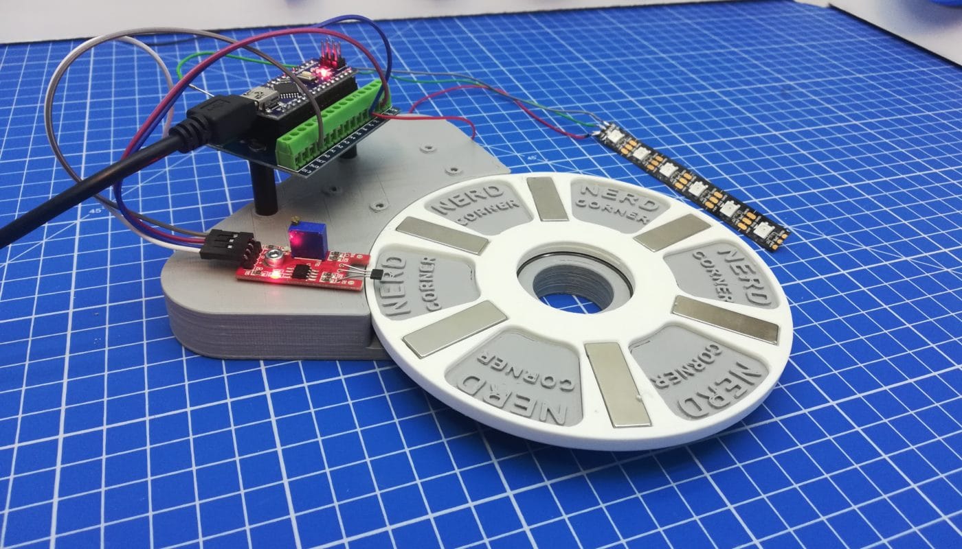
We built a test bench to detect a rotary movement. We call it the Hall Sensor Movement Detection. The necessary parts were 3D printed. You find the 3d parts at the end of this parts in the “Download files” section. The aim of the Hall sensor detection wheel is to detect a rotation and to keep the LEDs continuously lightning during the rotation. We need this set-up for our project to build a prayer wheel, because we are going to use the Arduino code here for the prayer wheel.
This might also be interesting for you: Simple guide on how to use a Hall Sensor with an Arduino
List of components
- Arduino Nano
- Nano Terminal Adapter
- 6 magnets
- Hall sensor KY024
- LED strip
- Jumper cables
- Screws 2x M2 and 1x M3 for the sensor
- Deep groove ball bearing 6807 2RS / 61807 2RS 35x47x7 mm
- 3D printing test setup (STL files in Download section)
Construction of test bench
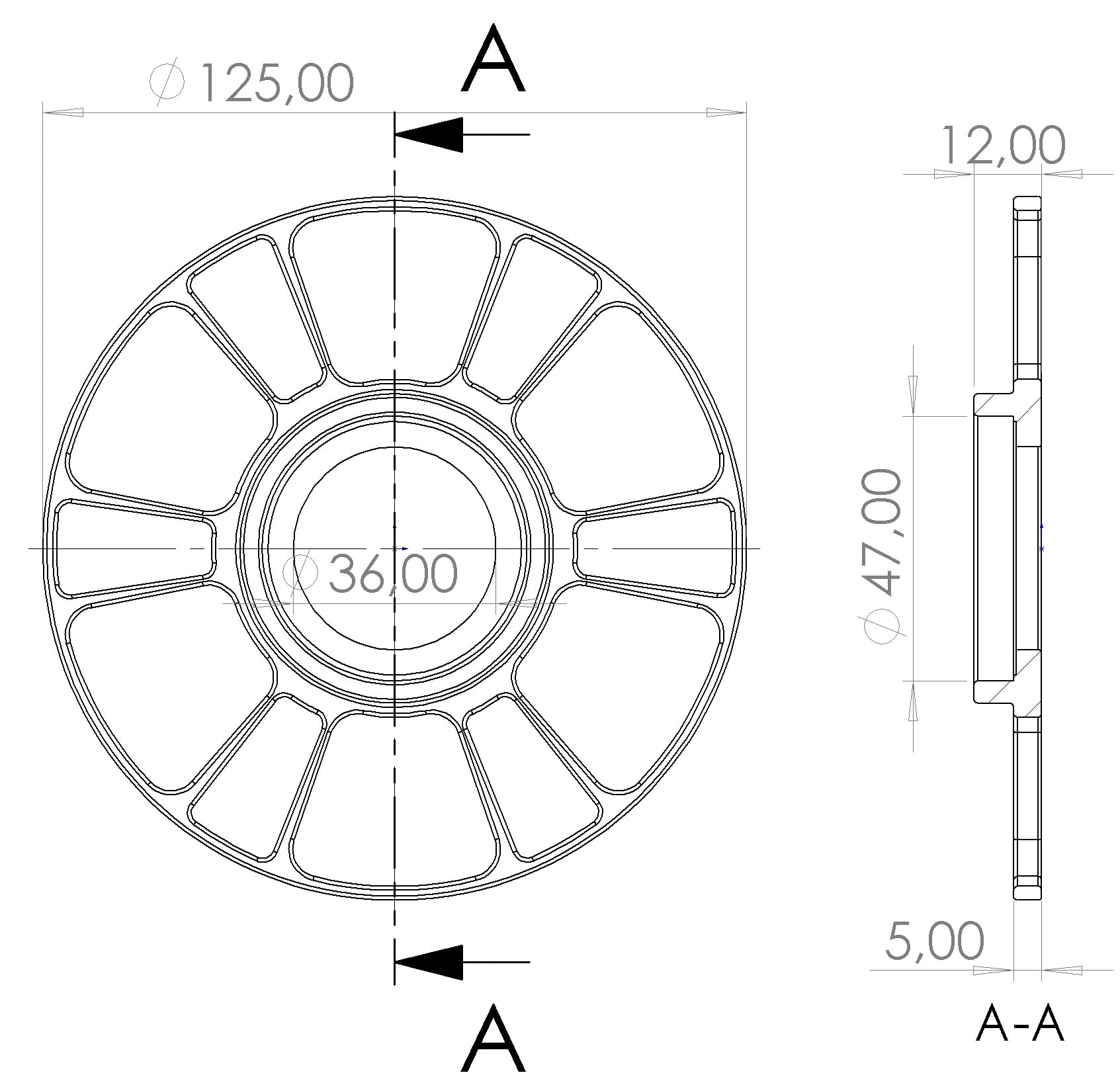
First we glued the 6 magnets into the 3D printed wheel. Make sure that the magnets are aligned homogeneously. Then the deep groove ball bearing is inserted into the detection wheel. The wheel can now be connected to the 3D printed bracket. Next we attach the Hall sensor KY-024 to the bracket. The Arduino Nano is plugged onto the adapter terminal and also attached to the bracket. The LED strip does not have to be attached separately. So you can start with the wiring.
Wiring
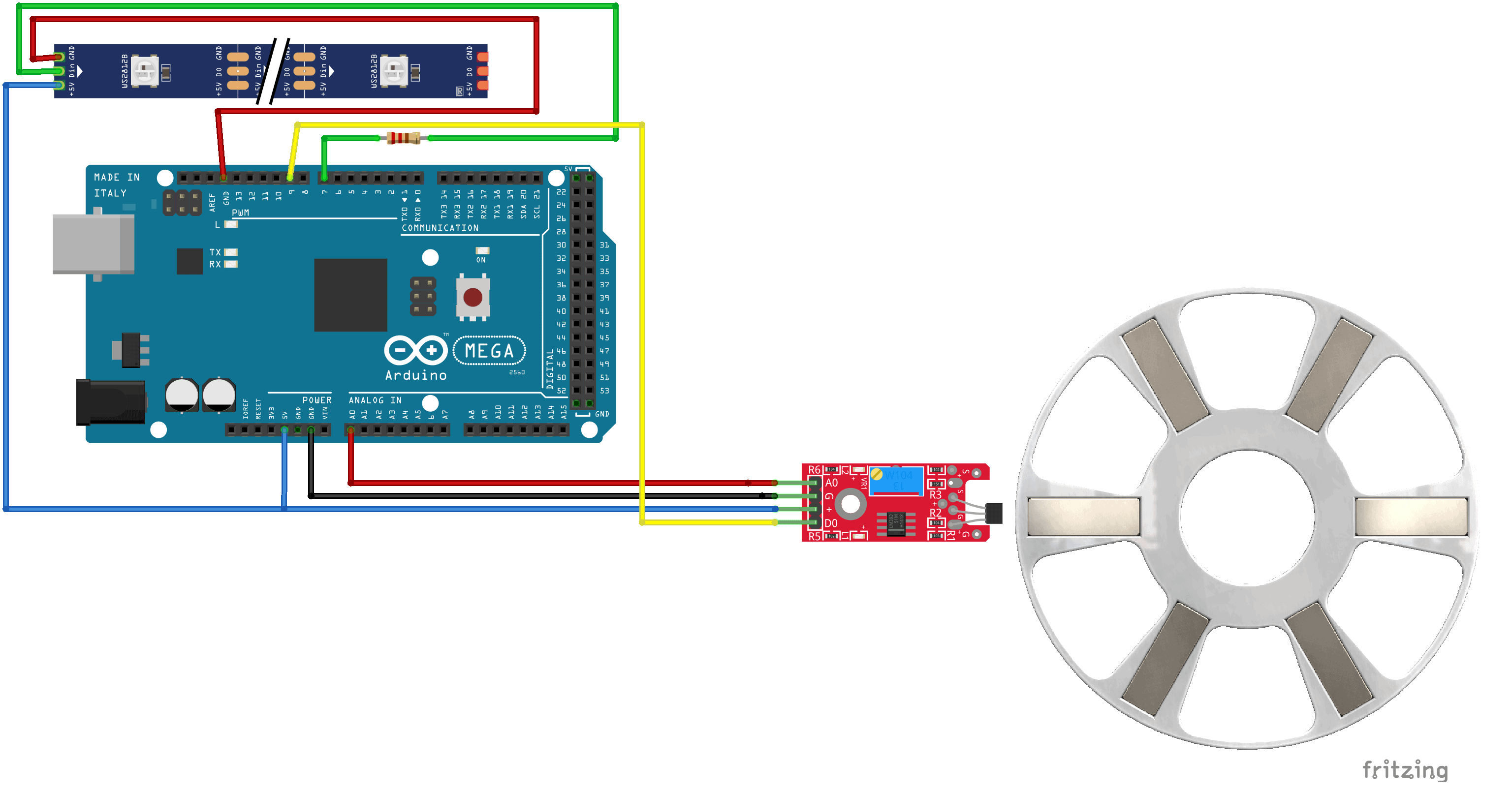
The wiring is not very difficult. Proceed according to the fritzing sketch. Connect the 4 jumper cables to the pins of the Hall sensor KY-024 and connect them to the Arduino Terminal Adapter. The 5V output of the Arduino is shared with both the Hall Sensor and the LEDs. Since there are only a few LEDs, no external power supply is required. For the LED strip you may have to solder them. We recommend to use a 220 Ohm resistor for the digital input of the LED strip.

Arduino Code Simple (with digital input)
In this code example, the Hall sensor KY024 sends the digital value 1 (HIGH) if there is a magnet or 0 (LOW) if no magnet is nearby. As soon as a HIGH is detected, the LEDs start to light up. But if the a magnet stops in front of the Hall sensor, it will send a HIGH constantly and the LEDs won’t stop lightning.
#include <FastLED.h>
#define LED_PIN     7
#define NUM_LEDS    6

CRGB leds[NUM_LEDS];

int digitalPin = 9; // Hall magnetic sensor input 1 (high) or 0 (low)
int digitalInputValue ; // digital readings

void setup ()
{
  FastLED.addLeds<WS2812, LED_PIN, GRB>(leds, NUM_LEDS);
  pinMode (digitalPin, INPUT);

  Serial.begin(9600);
}

void loop ()
{

  digitalInputValue = digitalRead(digitalPin) ;
  Serial.println(digitalInputValue); // print value
  if (digitalInputValue == HIGH)
  {
    for (int i = 0; i <= 5; i++)
    {
    leds[i] = CRGB ( 255, 0, 0);
    FastLED.show();
    delay(40);
    }
  }

  else if (digitalInputValue ==LOW)
  {
    for (int i = 0; i <= 5; i++)
    {
      leds[i] = CRGB ( 0, 0, 0);
      FastLED.show();
      delay(30);
    }
  }
}
Arduino code more advanced (with analog input)
This code is a bit more advanced. The goal for the Hall Sensor Movement Detection is to let the LEDs light up as soon as a rotary movement is detected. Even if a magnet stops directly in front of the KY024 Hall sensor, the LEDs must not light up, because there is no movement.
For this reason, the analog value of the Hall sensor is considered instead of the digital value. If the analog value changes, a rotary movement takes place. A small offset has been integrated to compensate minor fluctuations that occur even without a rotary movement. A counter was programmed as a double safeguard, which also counts how often the analog value changes. The double protection is intended to prevent the Hall sensor from detecting a magnetic field at a standstill.
#include <FastLED.h>
#define LED_PIN 7
#define NUM_LEDS 6
CRGB leds[NUM_LEDS];


int analogPin =A0;
int analogVal; // analog readings
int detector =0;
int firstVal=0;
int HIGHcount=0;


void setup() {
  FastLED.addLeds<WS2812, LED_PIN, GRB>(leds, NUM_LEDS);//pinMode (led, OUTPUT);
  pinMode (analogPin, INPUT);
  Serial.begin(9600);

}

void loop() {
  analogVal= analogRead(analogPin);
  detector = abs(firstVal-analogVal);  //if there is a difference >0 then the wheel might be spinning
  firstVal=analogVal;

  if (detector>4)   //offset = 4 can be adjusted
  {
    HIGHcount++;  //counting the high to eleminate false positives
    }
  else if (detector<=10)
  {
    HIGHcount=0;
  }

  if (HIGHcount>1)
  {
    YellowToRed(0);
    delay(1000);
    HIGHcount=0;
    }

  else
  {
     for (int i = 0; i <= 5; i++)
  {
    leds[i] = CRGB ( 0, 0, 0);
    FastLED.show();
    delay(30);
  }
    }

}


void YellowToRed(int colorStep)
{
  for( colorStep; colorStep<250; colorStep+=5 ) {

      int r = 255;  // Redness starts at zero and goes up to full
      int b = 0;  // Blue starts at full and goes down to zero
      int g = 255-colorStep;              // No green needed to go from blue to red

      // Now loop though each of the LEDs and set each one to the current color

      for(int x = 0; x < NUM_LEDS; x++){
          leds[x] = CRGB(r,g,b);
          leds[x].maximizeBrightness(255-colorStep);
      }

      // Display the colors we just set on the actual LEDs
      FastLED.show();

      delay(50);
  }
}
Pictures of the Hall Sensor Movement Detection


One thought on “Hall Sensor Movement Detection”