
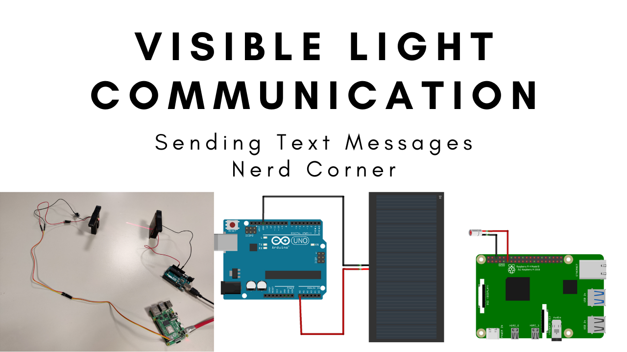
I like the idea of sending data via visible light. In general, Li-Fi (Light Fidelity) and VLC (Visible Light Communication) are heavily discussed at the moment. VLC is a visible light communication, which means it is primarily a cable replacement, while LiFi is a similarity to WiFi. A LiFi device would be a kind of Internet-enabled router that transmits data via light signals instead of radio frequency signals. Currently, however, no company has developed or is selling a Li-Fi router. VLC technology is used prominently at the moment by Elon Musk’s StarLink project. This allows satellites to exchange data using laser beams. I have replicated that in a simplified way in this blog article.
At first, I only want to transmit individual text messages in one direction. In a next step this can then be extended to transmit whole files bidirectionally. To receive the messages, I chose an Ardunio, because unlike the Raspberry Pi, it has analog inputs and can thus be easily connected to analog sensors. For sending, a Raspberry Pi is suitable, since only digital pins are needed here and a Pi can generally transmit data more efficiently and faster. This has already been tested in the previous posts about defining a clock frequency for the Arduino and the Raspberry Pi. All scripts to run the VLC communication can be downloaded at the end of the article. The following three blogposts are directly related to this project:
===> UPGRADE: SENDING ALL KINDS OF DATA WITH VISIBLE LIGHT COMMUNICATION
How to program the clock frequency of the Arduino: Use timer interrupts as clock frequency.
How to program the clock frequency of the Pi: Precise timer function in C for the Pi.
How to prevent errors in data transmission: Using CRC to detect corrupted packets.
List of components
- Arduino Uno
- Raspberry Pi
- 5V Solarcell
- 5V Laserdiode
- Jumper cables
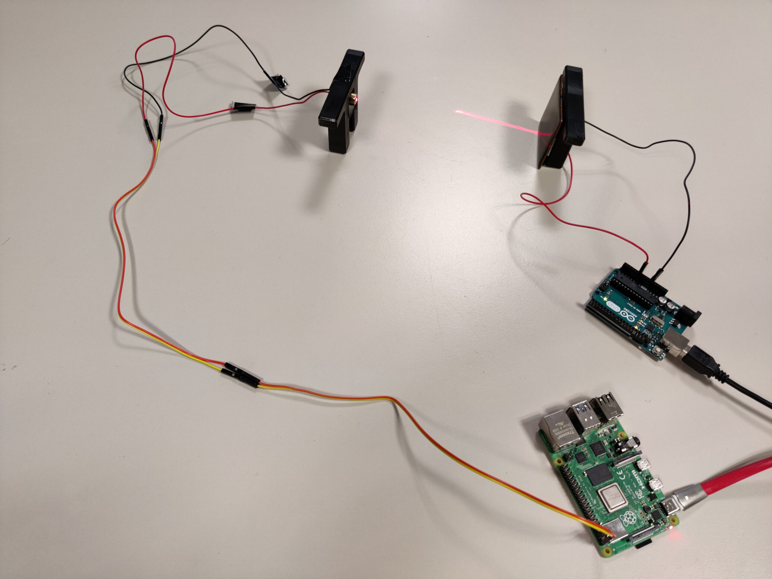
Wiring for the visible light communication

The wiring is rather simple. The 5V solar cell is very well suited to detect light signals. Therefore the solar cell is connected to the receiver, which is the Arduino. The ground of the solar cell is connected to a ground of the Arduino. The positive line of the solar cell is connected to an analog pin of the Arduino. Here, for example, A0 is suitable.
From the Raspberry Pi the messages are transmitted to the Arduino via light signals of the laser. For this, the ground of a 5V laser diode is connected to a ground pin of the Pi (see graphic). Then the positive line of the laser diode is connected to one of the digital pins of the Raspberry Pi. Here I chose the GPIO17 pin, which corresponds to pin 0 in the “wiringPi” library (see graphic).

As an alternative to the laser and the solar cell combination, an LED and a photoresistor can also be used. However, a laser is better suited for faster and more precise data transmission. In addition, a solar cell offers a large area to detect the laser beams.
Modulationtechnique On-Off-Keying
The text messages are transmitted in binary code as “1” or “0”. There are different ways to modulate this data. One of the simplest possibilities is to set an identical clock frequency for the transmitter and receiver. Then either a “1” or a “0” is transmitted in each clock pulse.
The procedure is called aplitude shift keying. If the laser diode illuminates the solar plate particularly strongly, this is detected by the receiver as a binary “1”. If the laser diode shines only weakly, it will be detected as binary “0”.
In fact it makes sense not to let the laser diode shine at all for a binary “0”. This is called On-Off keying. This is a simplification of amplitude shift keying. The following graphic illustrates the difference between amplitude shift keying and on-off keying.

That means, whenever the solar cell detects light, a corresponding voltage value is passed to the analog pin of the Arduino. If this voltage value exceeds a predefined value, the Arduino registers it as a binary “1”, otherwise as a binary “0”. It makes sense to adjust the predefined value to the daylight. Possibly with the help of an additional light sensor.
Arduino code to receive messages
//This is the "real" loop function
  switch (state)
  {
    case 0:
      //looking for synchronization sequence
      synchro_Done=false;
      lookForSynchro(data);

      if (synchro_Done== true)
      {
        state=1;
      }
      break;
    case 1:
      //receive Data
      receiveData_Done =false;
      receiveData(data);

      if (receiveData_Done==true)
      {
        state=0;
      }
      break;
  }
The software of the Arduino is basically built as a state machine. There are two states. One state for synchronization and one for reading the text message. In the state synchronization the receiver waits for a fixed bit sequence (preamble) for example “101010101111111111”. This sequence means that the receiver must listen now because a text message follows. The complete Arduino code can be downloaded at the end of the article. The following graphic shows the exact structure of the data packets.

As soon as the preamble is recognized, the receiver automatically switches to the second state and receives the actual message. However, the first 16 bits of the text message correspond to a decimal number, which tells the receiver how many characters the incoming text message contains. When this number is reached, the text is printed in the Serial Monitor of the Arduino and the state changes back again. Now the synchronization sequence is awaited again. The complete software code can be downloaded at the end of the blog article. To improve the transmission quality, a cyclic redundancy check (CRC) can be performed as shown in the following graphic.

Raspberry Pi code to send messages
//Read message
        char msg[3000];
        int len, k, length;

        printf("n Enter the Message: ");
        scanf("%[^'n']",msg);

        len=strlen(msg);


        int2bin(len*8, 16); //len*8, because 8 bits are one byte

        for(k=0;k<len;k++)
        {
                chartobin(msg[k]);
        }
The program code of the Raspberry Pi must be written in C. Python would be too slow and would not achieve a stable clock frequency for sending the data. The complete program code can be downloaded at the end of the article. In order for the Pi to control the laser diode the “wiringPi.h” library is needed. With “digitalWrite(0, HIGH)” the diode can be switched on and with “digitalWrite(0, LOW)” it can be switched off. Important: Please don’t forget the “wiringPi” library when compiling! The command is: “gcc -o simpleLaser simpleLaser.c -lwiringPi”.
At the beginning the program asks for a text message using the printf function. This is read in and stored by a scanf function. Then each letter is converted to binary code and stored in an array. The conversion is shown in the following graphic. At the end, the binary code is transmitted from the array in a fixed clock pulse. The laser diode is switched on for a binary “1” and off again for a binary “0”.

Conclusion on the Visible Light Communication for Arduino
The transmission of text messages by means of visual light communication works excellently. Thanks to the cyclic redundancy check, it is also absolutely error-free. However, the benefit of one-dimensional message communication is rather low. It would be better if any kind of files could be transmitted and that in both directions. An update will probably follow soon.
Download files


Hi, I am trying to create the same thing but with my own code but that code is working with LDR Sensor and not with 5V solar cell please would you tell me which solar cell you used in this project because my solar cell is not able to detect laser but it is detecting flashlight (I have to put it too close to solar cell to detect it)
Did you try it with polycrystalline or monocrystalline?
There is nothing mention as polycrystalline or monocrystalline. I bought it from local shop so please would you suggest me which one should i use? and please give me any reference if possible.
It is polycrystalline
When I run the program for the simple laser, i keep getting undefined reference to ‘wiringpisetup’. Although i have already installed the wiring pi package on the raspberry.
Any Help?
Thanks
Hey Jana,
you have to add -lwiringPi to the compiler command. Can you check please, if this solves your issue?
Can you guide me how to do it?
What have i done is that i went to Build -> Set Build Commands->Under the build command i wrote “gcc -o simpleLaser simpleLaser.c -lwiringPi”, and in working directory i wrote -lwiringPi
I keep getting “Failed to change to the Working Directory”
Any help?
Thanks
I think i have solved that since the error stopped showing, but when i execute it says Permission denied
Hi,
I tried to run the Raspberry Pi code but keep getting a syntax error with the first line. It keeps returning an error with a caret under the word “result”. Any help would be appreciated. Thanks,
char result[3000]={‘1′,’0′,’1′,’0′,’1′,’0′,’1′,’0′,’1′,’0′,’1′,’1′,’1′,’1′,’1′,’1′,’1′,’1′,’1′,’1’};