If you want to achieve a regular time interval with the Arduino you can simply use the delay() function. This will pause the program of the Arduino for the appropriate amount of time. If the requirements are higher you can also use millis() or nanos() as timer. The delay() and millis() functions are probably sufficient for most applications, but if you don’t want to pause the whole program or achieve a 100% exact clock time it makes sense to use Arduino Timer Interrupts. We explain what timer interrupts are and how to use them. You can find the Arduino code at the end of the post.
This might also be interesting for you: How to control an Arduino via Bluetooth
List of components
- Arduino Uno
- LED
- 220 Ohm resistor
- Wires
- Breadboard
What is a timer actually?
A timer is basically nothing else than a certain register in the microcontroller, which is increased (or decreased) continuously by 1 under hardware control. Instead of coding instructions in the program that are executed regularly and increment a register by 1, the microcontroller does this all by itself!
This becomes useful, if an action is executed at certain counter values. One of these ‘certain counts’ is for example the overflow. The count register of a timer can not be incremented arbitrarily long. E.g. the highest count that an 8-bit-timer can reach is 2^8 – 1 = 255. The next incrementing step is not 256, instead an overflow occurs, which makes the timer become 0 again. This is the magic! We can configure the controller so that an interrupt is triggered when the timer overflow occurs. We can write code in the Arduino program what should happen in case of an interrupt. For example, we can make an LED light up or query a certain sensor value.
Arduino Uno Microcontroller ATMEGA328P
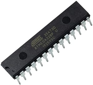
- 8 Bit-Timer0: used for functions millis(), micros(), delay() and for PWM at pin D5 and D6
- 16 Bit Timer1: Use e.g. for the Servo, VirtualWire and TimerOne library and for PWM at pin D9 and D10
- 8 Bit Timer2: Used for function tone() and for PWM at pin D3 and D11
How to vary the clock speed?
The system clock of the Arduino Uno is 16 MHz (CPU frequency). This means Timer0, Timer1 and Timer2 increase 16 million times per second. For example, the 8 bit timers count from 0 to 255 each time. At 256 an overflow occurs and the timers start again from 0. This means 16000000/256 = 62500 overflows per second (62.5kHz clock rate). This is likely too fast for most timer applications!
Therefore there is a trick to slow down the clock rates. You use a so-called prescaler. A prescaler can be set to the values 1, 8, 64, 256 or 1024. It allows you to divide the system clock (16MHz) by the selected factor and set a lower clock rate for the timers. For example, a prescaler of 1024 would increase the timer registers by 1 only at the 1024th system clock pulse. This would be 16000000/1024=15625 increments per second and thus with an 8 bit timer 15625/256= 61.035 overflows per second (~61 Hz clock rate of the timer).
Practical example LED should light up with 50Hz
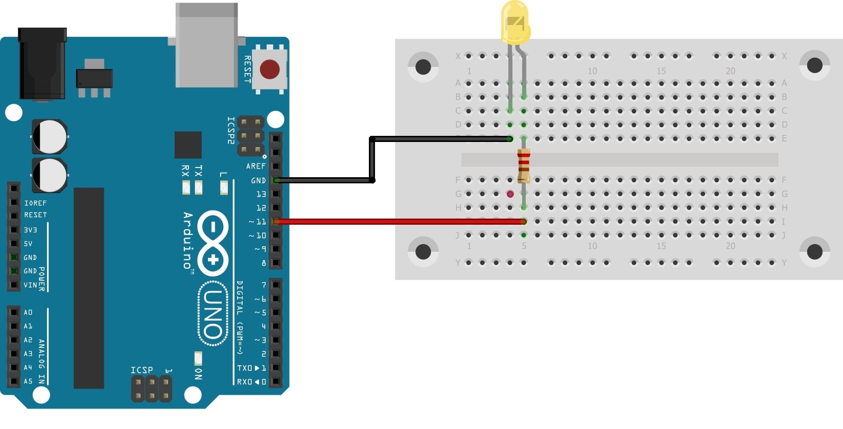
In the following, the triggering of Arduino Timer Interrupts is shown with the 16-bit timer1. With this a LED should light up in a 50 Hz cycle. Schematic, Arduino code and pictures are also included. (The procedure for the 8 bit timer0 and timer2 is analog.) For the time controlled pulse you need the so called “CTC Mode”.
In CTC mode (“Clear Timer on Compare Mode”) the counter is cleared when the value of the counter (TNCT1) matches either the value of the OCR1A register or the value of the ICR1 register (in our case OCR1A). So the OCR1A register determines the maximum value of the counter and thus its resolution.
The 16 Bit Timer1 needs the following registers
- Timer Counter Register 1: TCNT1
- Output Compare Register A: OCR1A
- Timer Counter Control Register A: TCCR1A
- Timer Counter Control Register B: TCCR1B
- Timer/Counter Interrupt Mask Register: TIMSK1
- (For Timer0 and Timer2 the corresponding registers would be TCNT0 and TCNT2, respectively)
Calculate the OCR1A register for Arduino Timer Interrupts
The value of the OCR1A register depends on the desired interrupt frequency and the selected prescaler. The following formula applies:

We put our specifications into the formula:
- CPU frequency Arduino Uno: 16.000.000 Hz
- Desired interrupt frequency: 50 Hz (= 20 ms period duration)
- Possible prescaler: 1, 8, 64, 256 or 1024
Calculation example with Prescaler 1024:
OCR1A= (16.000.000 / (1024 * 50)) – 1 = 311,5
Calculation example with Prescaler 8:
OCR1A= (16,000,000 / (8 * 50)) – 1 = 39,999
ATTENTION: The OCR1A value must be less than 65.536 (2^16 )!
Therefore a prescaler 8 can NOT reach 10Hz interrupt frequency:
OCR1A= (16.000.000 / (8 * 10)) – 1 = 199.999
The value 199.999 is larger than the register with 65.536, therefore another prescaler must be used to reach 10 Hz
Instead a prescaler 64 for 10 Hz interrupt frequency:
OCR1A= (16.000.000 / (64 * 10)) – 1 = 24.999
If a Timer1 interrupt is now triggered, the program flow jumps to an interrupt service routine to be created “ISR(TIMER1_COMPA_vect)”. (See Arduino Code)
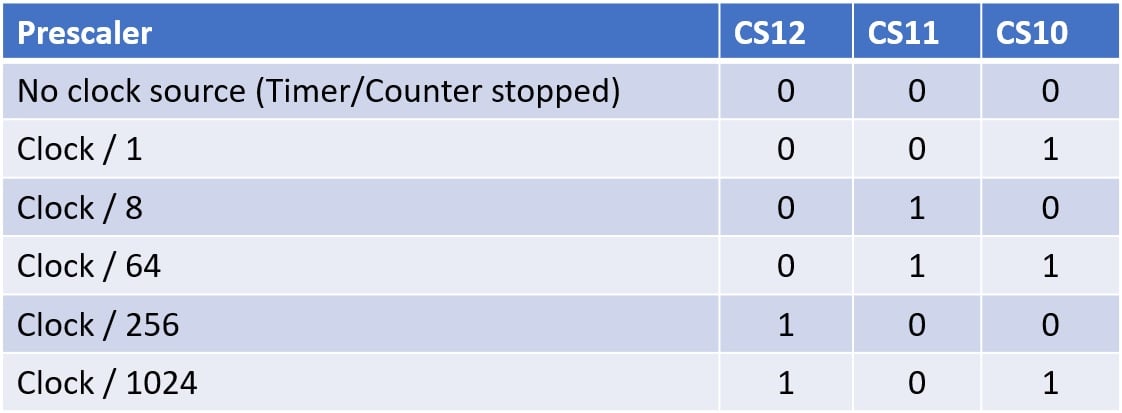
Bit combination for the desired prescaler
Arduino Timer Interrupts code for 50 Hz frequency
void setup() {

  pinMode(11,OUTPUT);  //LED pin (to blink in 50Hz frequency)

//START TIMER SETUP
//TIMER SETUP for highly preceise timed measurements

  cli();//stop all interrupts

  // turn on CTC mode
  TCCR1A = 0;// set entire TCCR1A register to 0
  TCCR1B = 0;// same for TCCR1B
  TCCR1B |= (1 << WGM12);

  // Set CS11 bit for prescaler 8
  TCCR1B |= (1 << CS11);

  //initialize counter value to 0;
  TCNT1  = 0;

  // set timer count for 50Hz increments
  OCR1A = 39999;// = (16*10^6) / (50*8) - 1

  // enable timer compare interrupt
  TIMSK1 |= (1 << OCIE1A);

  sei();//allow interrupts
  //END TIMER SETUP
}


ISR(TIMER1_COMPA_vect) {//Interrupt at frequency of 50 Hz
 //write your timer code here

 digitalWrite(11,HIGH);
 delay(15);
 digitalWrite(11,LOW);
}


void loop() {

//when the timer is over, your program will stop in the loop function and jump to the timer code.
//After the timer code it will jump back to the point where it left the loop function
}



Can you expand this? Maybe more examples with other prescalers?
So so useful, simple and easy language for timer information, thanks!