

In response to the extremely positive feedback on my quick connectors (Dupont connectors), I realized that their original purpose of only being used in the development environment has been extended to permanent use on various devices. Many people also expressed the wish to be able to mount the connectors permanently or screw them on. I have now fulfilled this wish.
You may also be interested in: 3D printed Dupont connector for jumper cables
Implementation of the Dupont connector
As with any new development or modification of an existing part, a number of decisions had to be made, but in this case not many were necessary.
- Number of fixing lugs: two or four
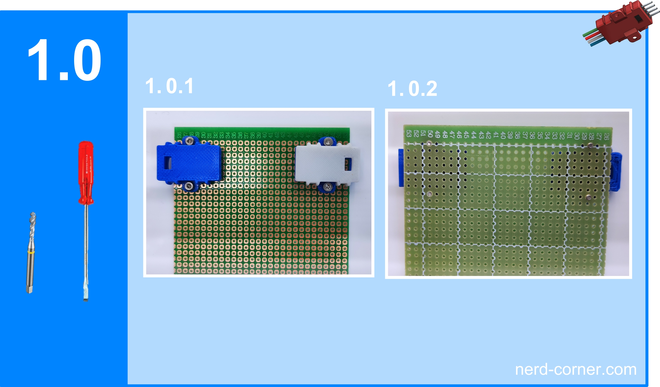
- Diameter of the fixing holes: 2.2 mm
- Cover removable after fastening: yes
With the number of fixing lugs, it is clear that a single lug will cause the housing to rotate around the screw if it is not tightened firmly enough. When the connection is inserted or removed, the housing tries to rotate around the screw. With two or more tabs, insertion and removal can be achieved without any problems, even if the screws are not fully tightened.
The diameter of the fixing holes has been set at 2.2 mm for M2 screws. Larger screws would make the lugs larger than the connector housing itself, and two M2 screws already provide sufficient holding force.
The decision as to whether the cover should still be removable after the connector had been attached was inevitable. As the clamping tabs of the cover protrude from the base of the housing, the fastening tabs had to be raised above the base anyway. If the lugs were flush with the base of the housing, the lid could rise by around 0.3 mm when the screws were tightened. Why were the fixing lugs not attached directly to the lid? The lid is not stable enough to support the side tabs. The distance between the surface and the base of the housing is 1.1 mm when screwed on, which is sufficient to remove the lid without any problems.
Regarding the fixing holes with a diameter of 2.2 mm: The hole spacing is always a multiple of 2.54 mm, which makes sense as the DuPont plugs also have a width and height of 2.54 mm. The hole spacing increases in proportion to the number of pins on the housing. A positive side effect: These distances also match the holes of a breadboard. In Figure 1.0.1 I have mounted two 4-pin connectors on a breadboard. For the attachment, I used the matching holes at the distance of the 4-pin connectors and cut threads with an M2 tap. As you can see, the screws hold perfectly without the need for a nut.
Yes, that’s almost it for this time – we’re actually finished now, but two things are still important to me. Firstly, I would like to talk about the versatility of the connectors. I’ve been using them for four years and am constantly discovering new ways to use them flexibly. Below are some examples with version one, which is identical to version 1.1 except for the screw-on option.
Figure 2.0.1 shows a 10-PIN connector with a 200 mm jumper cable. Figure 2.0.2 shows the difference between a 10-PIN connector with a 100 mm jumper cable and one with a 200 mm jumper cable.
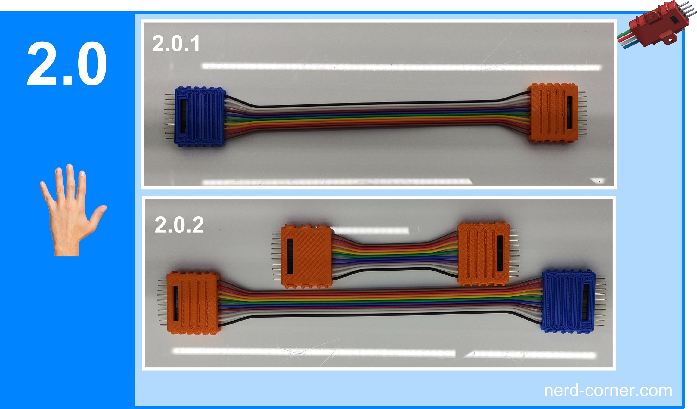
Figure 2.1.1 shows a 9-PIN connector on one side and three different connectors on the opposite side. Figure 2.1.2 shows this side enlarged. Here you can see the three connectors: a 4-PIN connector, next to it a 3-PIN connector and on the far left a 2-PIN connector. If you add up the pins of the three connectors, you get the nine pins as on the other side.
You have probably noticed that the DuPont plugs of the three connections are different. On the 4-PIN connector, all pins are male, i.e. pins. In contrast, all pins on the middle 3-PIN connector are female, i.e. sockets. The 2-PIN connector, which combines a male and a female connector, is particularly interesting. What is it all about? Here I would like to demonstrate the flexibility of Nerd-Corner’s tool-free connector system. As with the 2-PIN plug, these plugs can be used to install reverse polarity protection: The pin is the positive pole, the socket is the negative pole. The reverse is true for the mating connector, which means that the connection cannot be plugged in incorrectly!
The 2-PIN plug is the simplest example, but this principle can be applied to all plugs so that more complex protection systems can also be set up.

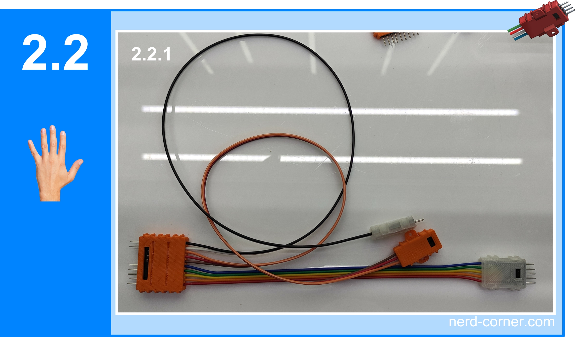
The structure in Figure 2.2.1 shows another way of creating a wiring harness. There is a 10-PIN connector on the left-hand side and a 5-PIN connector on the far right, connected by a 200 mm jumper cable. The orange 3-PIN connector is connected to the 10-PIN connector via a 400 mm jumper cable, as is the 2-PIN connector, but with a 500 mm jumper cable. This solution offers unlimited flexibility across the entire connector family and is completely tool-free.
Assembling the Dupont connector
I keep getting requests to build connector housings for 15 or 22 pins. Unfortunately, this is not impossible with this system, but it is a major challenge. The effort involved is disproportionate to the benefit – at least for me. I actually wanted to stop at the 6-PIN version, as the assembly requires a lot of fine motor skills and the holding force of the tabs decreases. I was able to solve the problem of the holding force from the 7-PIN version onwards by using a third tab, but this made assembly very difficult.
However, there is usually a solution, as can be seen in picture series 3.0.
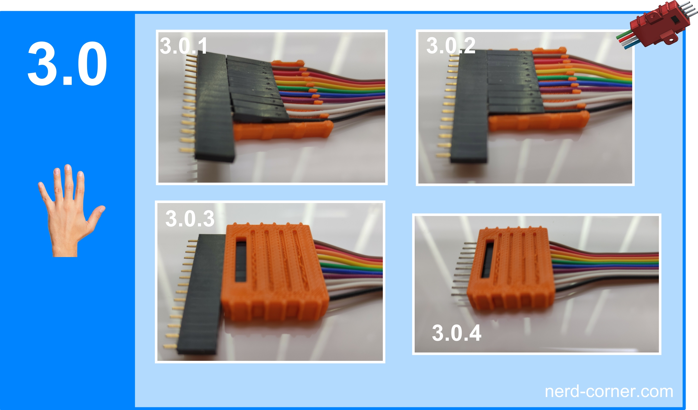
In picture 3.0.1 you can see that a female connector comes into play, as we are using male (pin) cables here. A pin header could be used instead for female cables.
The procedure for assembling with male cables (pins) is as follows:
- Push the cables into the socket strip.
- Press the inserted DuPont housings lightly into the base of the connector and press the cables into the recesses provided (see Fig. 3.0.1).
- Press the DuPont housings fully into the base of the housing and push them towards the internal stop strip. Then pull the cables backwards one by one – the socket strip should not be removed (Fig. 3.0.2).
- As soon as the DuPont plugs are fixed in the housing, the cover is fitted and snapped into place (Fig. 3.0.3).
- Finally, the socket strip is removed and the assembly is complete (Fig. 3.0.4).
Files to download


