
Many DIY projects are accompanied by chaos at the workbench. Screwdrivers, soldering irons, jumper cables, everything lies all over the place. Clean up is usually only at the end of the day or when the project is finished. I was annoyed by this mess, especially the jumper cables were everywhere. After I designed a connector as a soldering aid for jumper cables and LED strips, I came up with an idea with which I could both get the chaos under control and increase the stability of the jumper cable PINs. The idea was to use a Dupont connector.
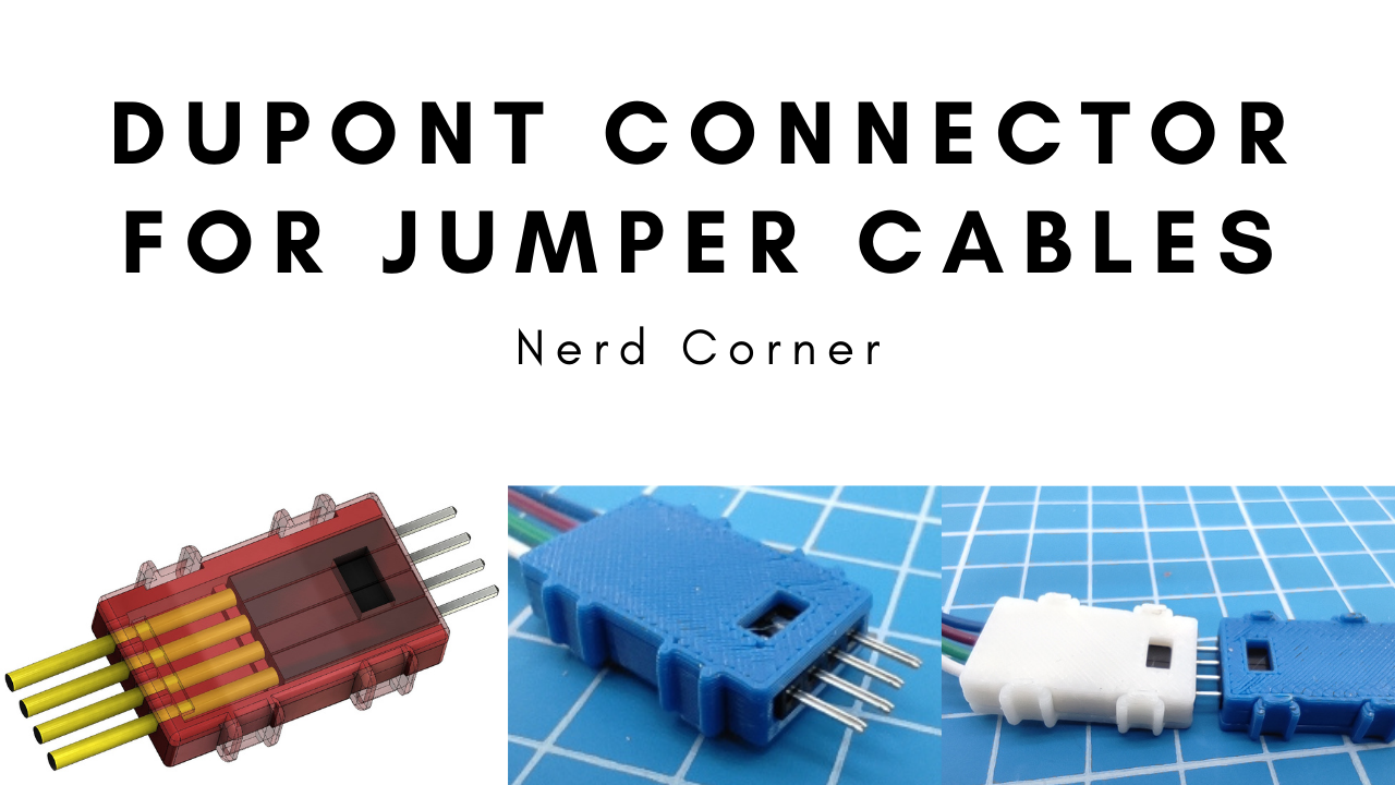
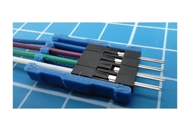
The following picture shows such a connection. I am absolutely thrilled with how practical these connectors are in everyday life. For example, several LED strips can be connected via a 4 PIN Dupont connector to a controller without any additional tools!
This might also be interesting for you: designed a connector as a soldering aid for jumper cables
List of components:
- 3D printer
- Filament PLA
- Jumper cables

CAD design for Dupont connector
As with any CAD design, you shouldn’t just start off without a plan, but rather clarify a few questions first.
- What manufacturing tolerance do the black housings of the jumper cables have?
- What lengths exist for the black housings?
- Are there different cable diameters?
- How big should the lug on the cover be?
- Which material should be used?
The measurements (with a digital caliper) from different manufacturers of the jumper cables showed that there were hardly any deviations. The biggest deviation was the length from 12 mm to 14mm. Since most of them have a length of 14 mm, this measurement was also used for my CAD design.
The goal was to design a quick connector, i.e. put the cable in, press the lid on and it’s done. With this I wanted to avoid screws, cable ties, hose clamps, gluing or soldering.
Material and Dimensioning
To achieve this, I decided to use retaining lugs or claws. For this you have to pay attention to the dimensioning and the choice of the material. Probably the best material would be nylon. Unfortunately I don’t have the possibilities to print with nylon. This would have required a closed construction space. The same goes for ABS the second best solution. That leaves only PET or PLA. I still had a larger supply of colorless PLA, so I decided to use PLA. Note at this point: The color additive in the filament influences the printing properties and not insignificantly! For functional prints I always choose colorless PLA.
To be able to put 4 jumper cables into the case, I chose an inner dimension of 10.6 mm. For the side walls I chose a thickness of 1.7 mm and for the bottom a thickness of 1.46 mm. The outer dimensions were 4 mm x 14 mm x 25 mm.
Lid construction
For the lid, the dimensions are identical to the housing, but with an addition for the protruding tabs with the lugs. The dimensions of the tabs are based on my previous experience. I decided to use a second pair of tabs because it increases the holding force and distributes the force better. Also, if one tab should break, the lid would still hold securely to the case.
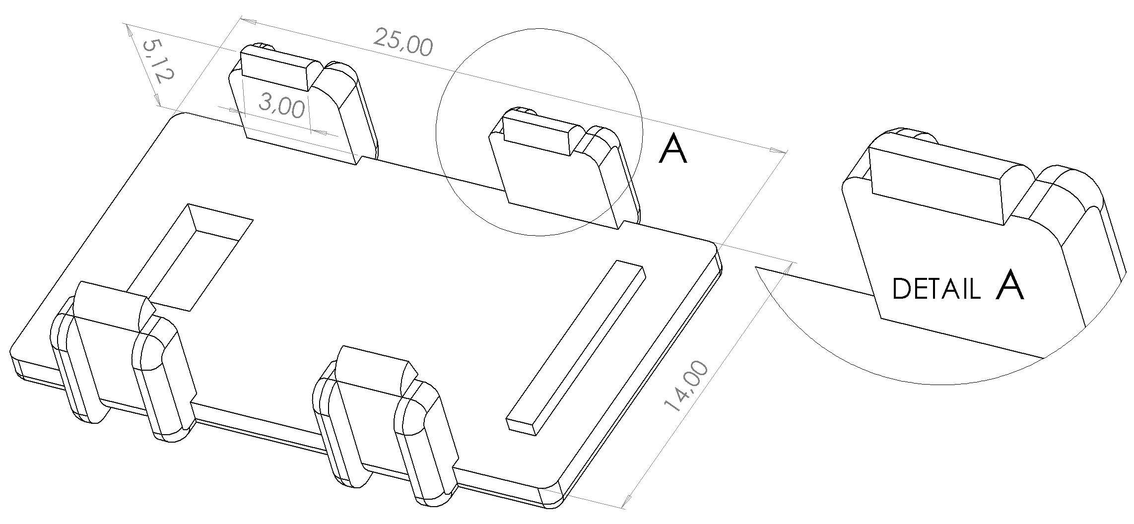
The shape of the lug at the end of the tab (Detail A) is important, as the 3D printer will not print this exactly as designed on the CAD.
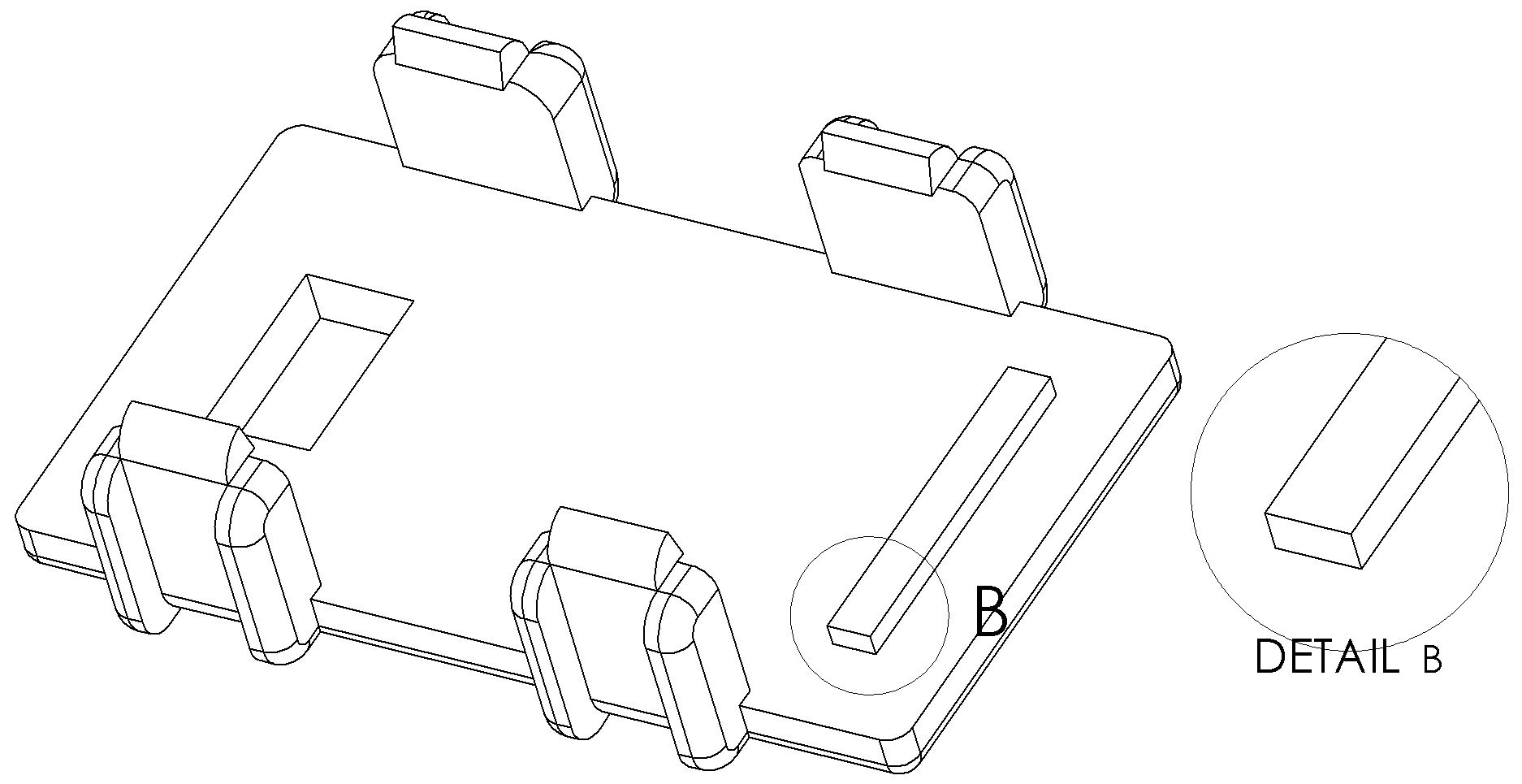
As shown in detail B, an elevation was constructed on the inside of the lid. This elevation helps to press the cables down slightly when the lid is pressed onto the housing. The cables are fixed in the housing and pull the housing towards the stopper (detail D). The additional tension secures the cable housing more precisely. This works because the pressing takes place behind the fastening in the housing and the cables have some distance to the bottom of the housing. However, the height of the pressure bar (detail B) must not be too large, otherwise the lugs of the tabs cannot click into place on the bottom of the housing.

The roundings on the cable seat (detail C) are used for easy insertion of the cables. The apertures or also called windows were originally intended for the opposite side of a connector as a holding point. However, I discarded this because the holding torque is more than sufficient. The rectangular apertures now help with orientation during assembly.
Assembly
The assembly is quick and easy. The first Dupont cable is placed from the front on one of the two side panels and the cable housing is pushed to the stop (detail D). Then hold the housing and pull on the cable to eliminate any gap between the crimp connection and the cable housing. Now press the cable into the cable guide on the connector housing. Do the same with cable number 2, 3 and 4 and then press the cover onto the housing until it clicks.

Applications for the Dupont connector
Originally I had constructed this connector design for a project with many 4PIN RGB strips. After a short time I realized how practical the design was. I can use it for the Arduino, sensors, LED strips, Raspberry Pi and much more and that without soldering or using other tools. Of course, I know that you always have to leave a gap of 2 PINs between the connectors on the Arduino, but this doesn’t really bother me in everyday life.

Advantages of the Dupont connector:
- Quick assembly
- Universal use
- Enormous holding force
- Easy to print
Disadvantages of the Dupont connector:
- Greater space requirement


This is just what I was looking for, but I’d really like a six-pin version (or the Fusion 360 project). I have a six-pin FTDI board that I’m going to accidentally break a pin on. So, I’d really like to extend those pins with an elegant solution like this.
Great work. I’ll watch for more projects here.
Excellent work my friend!
I really appreciate the explanation about the mechanical design.
Greetings from Brazil!
Hello friend,
Really appreciate the work done and also the mechanical design explanation!
Thank you very much.
Is it possible to share your CAD files? I had some ideas on variations of your connectors, what do you think?
How about doubling the inner space of the 3 pin to hold six dupoints in a 3×2 row matrix . I use various arduinos rev3, mini, etc. The cables loop every where. A dupoint cable tidy/holder for projects would be a handy tool. Other connectors to use as male and female input output sockets to fit inside as one needs in there projects. Even have connectors as multi pin matrix’s of various configurations 2×2, 3×2, 3×4, 2×5 etc to double, triple, or to quadruple the dupoints held inside.
Hi
Can You make 8 pin in configuration of 2×4 and 10 pin in configuration of 2×5?
Thank You
Any tips on printer settings? I’m having trouble with these fitting, changed to 90% flow and thinned out the walls. They still need a lot of work after printing and don’t fit that great. I’m sure it’s my fault.
So I decided to just use the bottom piece and then use shrink tubbing to hold the pins in. Works great and looks good too! The shrink tube gives a smooth surface for writing with a sharpie. Thanks for the work you put into this!
thanks. my students will enjoy this.
Is the hole in the “lid” there for some purpose other than an orientation reminder?
Have you considered creating a set of connectors with orientation tabs to prevent plugging it in the wrong way? This would be especially useful on cable-to-cable connections but could also potentially be useful on a connector going to a board (assuming the connector was at the edge or some other place where a protrusion would stop it from going in the wrong way).
why is there a hole
Would it be possible to get the files as STP rather than STL? Thanks
What a brilliant idea. I have a dexterity issue in my hands and fingers due to a neuropathy and inserting dupont wires is a bit of a nightmare. For single ones I normally use pair of snipe nose pliers to be able to grip them. These other designs for multiple wires will be an absolute saviour, thank you.
Really well done!
However, I’m printing on an Elegoo Neptune 4 Pro with PTEG and find the 4 pin connector is like .15mm too narrow for the 4 dupont ends to nest into the connector?? Any suggestions?
Thanks!
I was lucky to find that page right at proper time for my projects.
Thank you VERY much.
These designs I am sure will help a baby boomer with little to no experience complete projects without the need for fragging components with very poor soldering techniques. I have one project in mind where I have nuked a PCB.
https://www.thingiverse.com/thing:4585839
Thank you also for making the model’s free.