

Often you don’t need a large power source to reliably charge an 18650 battery. Unfortunately, suitable, small solar panels are difficult to find – many are polycrystalline, have no housing or are merely laminated and fitted with simple eyelets for fastening. However, this is rarely ideal for stable and weatherproof outdoor installation. If you want a clean, durable installation, you need a robust housing with an adjustable bracket. For my outdoor applications, an output of around 1.5 watts is usually sufficient – a monocrystalline 2-watt panel with a corresponding solar panel mount is exactly the right choice.

This might also be interesting for you: Do it yourself powerbank with voltage regulator and voltmeter
Planning and choice of material
Before I start building, I first think about where the solar panels should be mounted: One on the garden shed, two on the balcony railing and one on the weather station mast.
The garden shed has a straight wooden wall, which makes a flat bracket necessary. The balcony railing and the mast, on the other hand, each have a diameter of 30 mm – a bracket with a rounding is required here. So I currently need two different types of mounting.
I use a monocrystalline 2-watt module with an output voltage of around 6 V as the solar panel (see Figure 1.0.1). For the electrical connection to the panel, I opted for a standard 5.5×2.1 mm hollow socket (see Fig. 1.0.2). Cables and screws are not included in the illustration as they may vary depending on the application. The panels are available in packs of five or ten from various online retailers. Their dimensions are 120 × 110 mm (length × width), whereby the height can vary between 1.3 mm and 1.8 mm.

Construction of the housing
The central component for the solar panel mount is the frame. It provides both the stability and the sealing function of the housing. The frame must be torsion-resistant, be able to accommodate all the necessary threads and still remain compact. The solar panel is pressed into its seat from behind with strips so that it is tightly sealed at the front.
Several screws are required to create an even contact pressure (see Figure 2.0.1).
There is a cover on the back (Fig. 2.0.2), which is reinforced in an X shape for stability. This cover also accommodates the hollow bushing (5.5 × 2.1 mm), which is later attached with a small bridge. One of the four pressure bars that press the panel into the frame can be seen in Figure 2.0.3. The joint holder (Fig. 2.0.4) is used to attach the panel to railings or walls. This serves as a holder for the retaining lever, which holds the housing securely in place and allows flexible alignment.


Figure 2.1.1 shows the holding arm for railing attachment with a 30 mm diameter at the end. The counterpart for the holder can be seen in Fig. 2.1.2. The bridge (Fig. 2.1.3) for attaching the hollow bushing to the cover.

3D printing of the components
For 3D printing, I chose the following print orientations for the Prusa MK4 (see Figures 3.0.1 and 3.0.2).
Particularly important: The bar must of course be printed four times, as it is used on all four sides of the solar panel.

Thread cutting
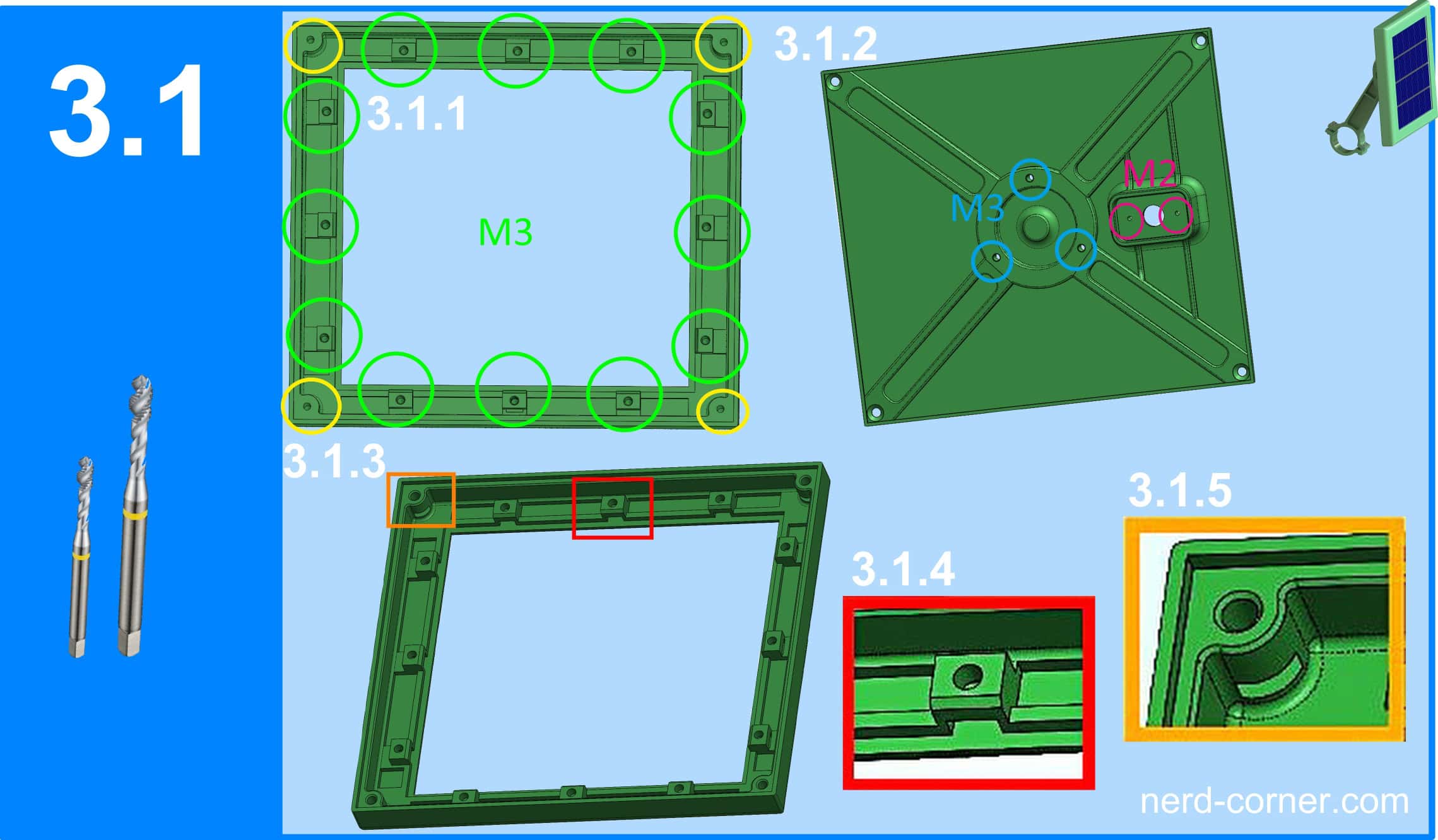
Now let’s move on to my favorite activity: thread cutting. Admittedly, there is a lot to do in the frame (see Figure 3.1.1): The green markings indicate 12× M3 threads, the yellow ones 4× M3 threads.
There is an alternative version of the frame for those who are not the biggest fans of thread cutting. This is equipped with slots to accommodate normal M3 nuts. The matching file is called: Deckel110x120_V1-2.stl (see Figure 3.1.3).
The recesses for the nuts are also clearly visible in Figures 3.1.4 and 3.1.5.
On the back cover (Figure 3.1.2), however, the cutting of threads can hardly be avoided: 3× M3 threads and 2× M2 threads are required here.
Alternatively, self-tapping screws can also be used – this saves tools and time.

Soldering and assembly
Once all 3D printed parts have been cleaned and threaded, the solar panel can be connected and soldered.
Electrical connections
The first hurdle is to find out where the positive pole is located on the panel.
There are only two soldering lugs on the back of the solar panel, but no labeling – so: plus or minus? To determine this quickly and clearly, we need a multimeter. If we set it to measure direct voltage (DC), it helps us to recognize the polarity.
Figure 4.0.1: The red wire (positive) of the multimeter is connected to one of the soldering lugs, the black wire (negative) to the other. If a minus sign appears in front of the measured value on the display, this means that the red wire is connected to the negative terminal – i.e. the opposite tab is the positive terminal of the solar panel.
Figure 4.0.2 shows the reverse configuration: the red wire is connected to the positive pole of the panel, the black wire to the negative pole. In this case, no minus sign appears in the display – the polarity is correct,
and we now know for sure where the positive pole of the solar panel is.

The hollow socket is now soldered to the solar panel. Figure 4.1.1 clearly shows which connections need to be connected.
Figure 4.1.2 shows the finished soldering in the installed state.
I have also soldered a diode to the positive pole of the hollow socket (see Fig. 4.1.3).
This protects against reverse current: if the connected load does not have its own protective diode, the solar panel would draw energy from the battery in the dark – and unintentionally work as a heater.
A typical example:
If a charge controller does not have an integrated diode, the battery can discharge the panel backwards in the absence of sunlight.
The installation direction of the diode is crucial so that the current can only flow in one direction.

Mounting the hollow bushing and inserting the panel
The installation of the soldered hollow bushing on the retaining bridge is shown in Figure 4.2.1.
The hollow bushing is pushed into the large opening of the retaining bridge until the thread protrudes on the other side. The nut is then placed on the thread and tightened – the result is shown in Figure 4.2.2. The solar panel is now inserted into the retaining seat of the frame (see Figure 4.2.3, red frame).
If you want to increase the tightness, you can apply some elastic adhesive evenly to the seat before inserting the panel. Once the solar panel is correctly seated, the first strip is placed in position and lightly tightened with a screw in the middle (see Figure 4.2.4, magenta circle). A side view is shown in Figure 4.2.5 to illustrate this.

Fastening the slats and screwing
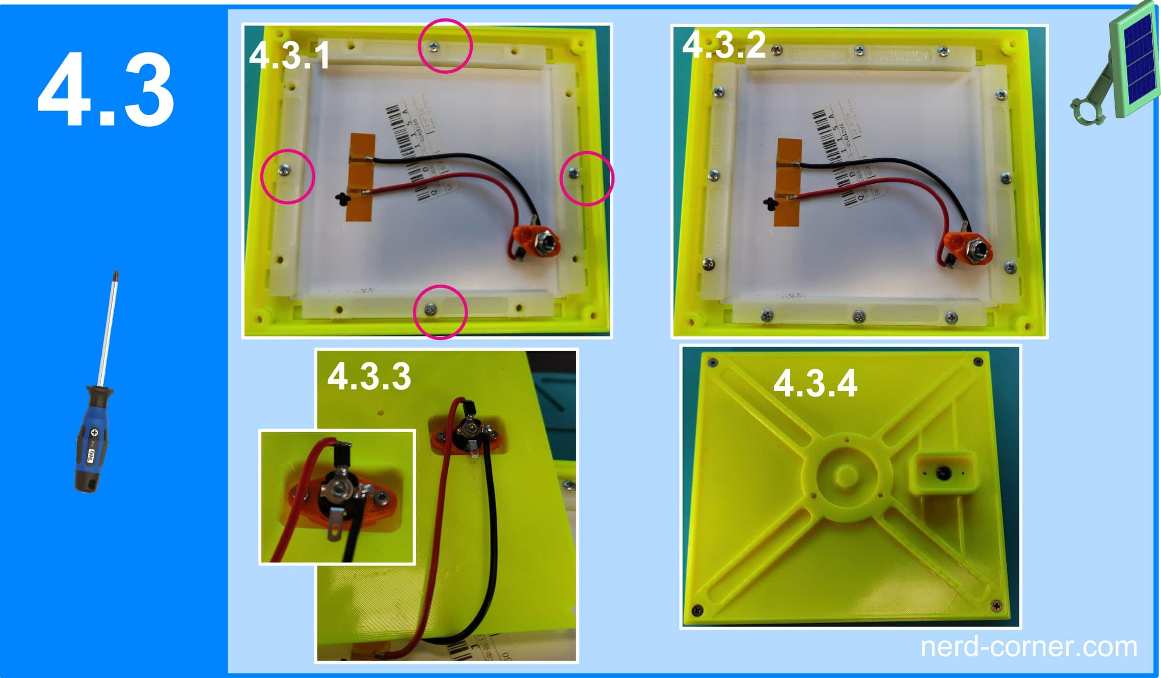
The remaining slats are attached one by one with the screw in the middle (see figure 4.3.1). Then insert the remaining screws, but do not tighten them yet (see figure 4.3.2). When the solar panel is evenly positioned, first tighten the middle screws of each strip.
Then tighten all the remaining screws and retighten them after a short time. If the solar panel still has some play, you can place some shims between the solar panel and the rail until it is firmly in place. Figure 4.3.3 shows how the hollow bushing and retaining bridge are attached to the inside of the back cover.
Finally, the back cover is screwed onto the frame with four screws (see Fig. 4.3.4).

Only a few steps are required to complete the bracket:
First, the M6 nut is pressed into the joint bracket (see figure 4.4.1).
The holder for the railing is then attached to the joint holder with an M6 screw (see Figure 4.4.2).
The joint holder is now screwed to the back cover with three M3 screws.
Do not forget: The M3 nuts must be pressed into the counterholder that will later be used for mounting on the railing (see figure 4.4.4).

Exploded view of the solar panel mount
For a better overview, there is an exploded view of the solar panel holder in Figure 4.5.1.

Note
Of course, there are also alternative mounting options. For instance, in a garden flower bed, plants may grow over time and gradually shade the solar panel. In this case, a holder with an aluminum rod and ground spike can be used (see Fig. 5.0.1).
On a balcony, the panel can be attached via flower boxes that cover the railing; here too, a holder with an aluminum rod is available (see Fig. 5.0.2).
Additionally, a holder designed for mounting on a wall or post is also provided (see Fig. 5.0.3).

Furthermore, I plan to design a solar panel holder with a built-in USB-C output.
The solar panel is an excellent addition for powering my small devices and outdoor sensors – and this holds true even in winter! Depending on your needs, you can either assemble the cables yourself or purchase them ready-made. In any case, the rule of thumb is: the shorter, the better.
Have fun building your own version – or perhaps this project has inspired you to create something entirely new.