

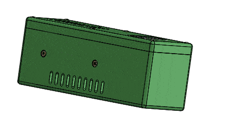
After building a simple powerbank, I now decided to combine a step-up module XL6009 with my existing powerbank. Fortunately, I had already constructed and tried three different case variations for the XL6009 in the past. The picture below shows these three different case designs. As usual, the cases can be downloaded individually via a link at the end of the post. The exact procedure for constructing the enclosures has already been described in detail in the article about the LM2587S.
You might also be interested in: DIY Powerbank with the Battery Shield V3 and Lipo Battery 18650

List of components:
- 2 x Hollow socket 5.5 x 2.1
- 1 x Battery Shield V3
- 1 x LiPo 18650 3500mAh
- 1 x rocker switch 250V/3A mounting dimension 15×10,5mm
- 4 x hexagon socket head screws M2 x6
- 6 x raised countersunk head screws M2 x 12
- 1 x module XL6009
- 1 x Mini voltmeter DSN – DVM – 368
- 7 x jumper cable
Implementation
Basically, the XL6009 differs from the LM2587S only in terms of current. The XL6009 provides an output voltage of 5V-35V and an input voltage of 3V-32V at 2.5A output current. To operate at 3A output current the XL6009 must be cooled with a heatsink. My choice fell primarily due to the small dimensions and the low price on this module. Since the capacity of the LiPi battery is limited, there is no need to install a too large step-up.
Construction
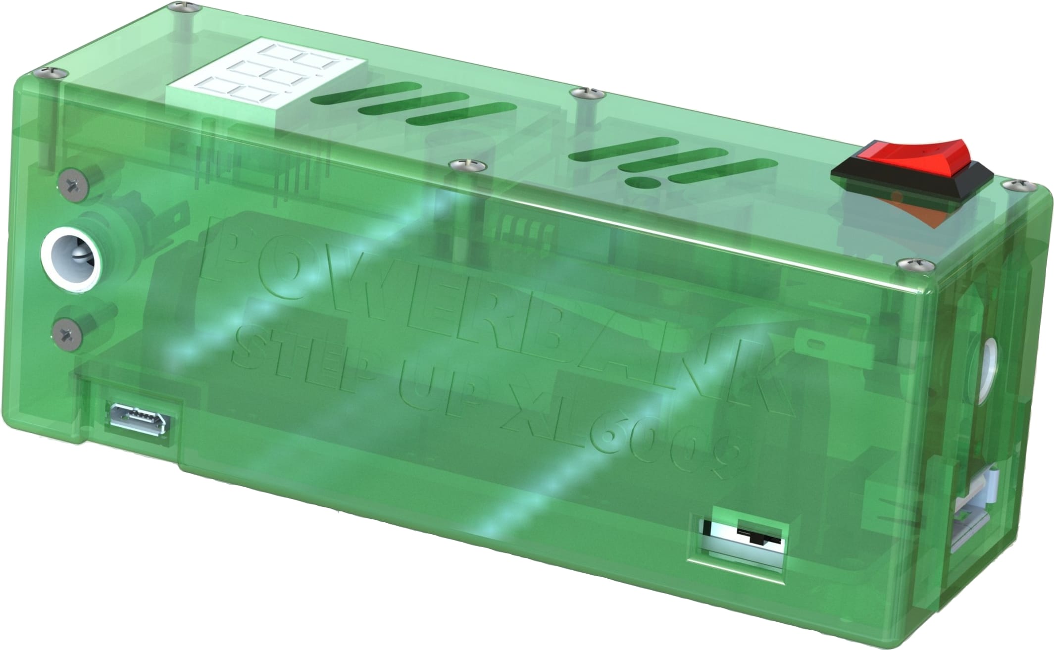
The Battery shield V3 has already been analyzed in detail here. Therefore we can start directly with the construction of the case. The case of the last powerbank is used as a basis, because the mount for the Battery shield V3 is already included. Now the two hollow sockets, the XL6009 and the mini voltmeter have to be integrated. There seems to be enough space for the hollow socket at the XL6009 output to be placed vertically above the USB Micro input.
For this project only the height of the case has to be increased. The raise also helps to fix the second hollow socket in the lid at the front. The position of the hollow socket with a mounting bridge is placed vertically as well. The hollow bushing for the XL6009 output is screwed from the outside. The hollow socket for the 3V output from the inside. This is important because two different hollow socket mounting bridges are needed. For a better overview the following illustration is provided:

I have added a new mounting part for the XL6009 module. It is a holder that is attached to the inner wall of the case. So the module can be screwed tightly from the outside. A disadvantage is the fact that the holder with module covers the LiPo and when changing the LiPo battery, the step-up must be removed at first. Ideally, though, the battery is rarely changed.
The lid was raised a bit compared to the simple powerbank and one or two crossbars were removed. This created space for the mini voltmeter. To be able to adjust the XL6009 without removing the lid, another hole was needed in the lid.
To set the hole as ideal as possible, it helps to assemble the case physically at first. So you can move the position of the XL6009 module on the mount a bit because the module has a 3mm hole and the mounting screws with M2 leave a little space.

To be able to turn the XL6009 on and off, a switch was still necessary. Here I opted for an ordinary toggle switch. Overall, I am satisfied, because the housing has increased by only 12mm compared to the other powerbank and the dimensions in width and length have remained the same.

Step by step assembly


Purpose of the powerbank
The powerbank obviously can charge smartphones and headsets via the USB A, just like any other powerbank. The 3V output can be used to power common flashlights or electronic modules. In addition, the adjustable voltage output can cover a range from 6V to 30V. There are many devices which are operated with 6V, 9V and 12V e.g. LED, radio etc..
I have specified the top voltage value up to 30V, but the XL6009 module could at least handle 35V. However, the mini voltmeter that I use is only specified up to 30V. Another reason is the Battery Shield V3 itself. For the Shield, the output is described as 5V and 3A, but the reality is lower than that. The reason is the internal voltage converter which brings the LiPo voltage to 5V.
The following table contains measured values that show the relationship (without internal voltage converter) between the increase of the ampere value at the input and the voltage value at the output:
| State of charge in volt | |||
| Volt for 1A | 3,2 | 3,7 | 4,2 |
| 6 | 1,88 | 1,62 | 1,43 |
| 7 | 2,19 | 1,89 | 1,67 |
| 8 | 2,50 | 2,16 | 1,90 |
| 9 | 2,81 | 2,43 | 2,14 |
| 10 | 3,13 | 2,70 | 2,38 |
| 11 | 3,44 | 2,97 | 2,62 |
| 12 | 3,75 | 3,24 | 2,86 |
| 13 | 4,06 | 3,51 | 3,10 |
| 14 | 4,38 | 3,78 | 3,33 |
| 15 | 4,69 | 4,05 | 3,57 |
| 16 | 5,00 | 4,32 | 3,81 |
| 17 | 5,31 | 4,59 | 4,05 |
| 18 | 5,63 | 4,86 | 4,29 |
| 19 | 5,94 | 5,14 | 4,52 |
| 20 | 6,25 | 5,41 | 4,76 |
| 21 | 6,56 | 5,68 | 5,00 |
| 22 | 6,88 | 5,95 | 5,24 |
| 23 | 7,19 | 6,22 | 5,48 |
| 24 | 7,50 | 6,49 | 5,71 |
| 25 | 7,81 | 6,76 | 5,95 |
| 26 | 8,13 | 7,03 | 6,19 |
| 27 | 8,44 | 7,30 | 6,43 |
| 28 | 8,75 | 7,57 | 6,67 |
| 29 | 9,06 | 7,84 | 6,90 |
| 30 | 9,38 | 8,11 | 7,14 |
One should not forget that with battery-powered voltage converters, the voltage drop during discharge is also a factor. In order to be on the safe side, I have installed a pico fuse with 2A in this powerbank. Attached is a table with ampere values that should not be exceeded by the consumer at the specified voltage:
| Volt | max. A consumer |
| 6 | 1,67 |
| 7 | 1,43 |
| 8 | 1,25 |
| 9 | 1,11 |
| 10 | 1,00 |
| 11 | 0,91 |
| 12 | 0,83 |
| 13 | 0,77 |
| 14 | 0,71 |
| 15 | 0,67 |
| 16 | 0,63 |
| 17 | 0,59 |
| 18 | 0,56 |
| 19 | 0,53 |
| 20 | 0,50 |
| 21 | 0,48 |
| 22 | 0,45 |
| 23 | 0,43 |
| 24 | 0,42 |
| 25 | 0,40 |
| 26 | 0,38 |
| 27 | 0,37 |
| 28 | 0,36 |
| 29 | 0,34 |
| 30 | 0,33 |


Thanks a million for the insights you share on your blog. I always wanted to build a powerbank myself!