

I have often thought that it would be extremely convenient to connect my Arduino projects with the Wi-Fi. At some point I randomly came across the WeMos D1 R2 and I am thrilled! In principle, every Arduino project can be realized with the D1 and you always have the possibility to use Wi-Fi. Probably the D1 will even displace the Arduino from the market in the future. In the following I explain the differences between an Arduino UNO R3 and a WeMos D1. Afterwards I describe the setup of the D1 with a simple example. In the example, a browser is used to control an LED, which is built-in on the D1.
This might also be interesting for you: How to control a fan with an Arduino!
List of components
- Arduino IDE (development environment)
- WeMos D1 R2
Differences between the WeMos D1 R2 and the Arduino UNO R3
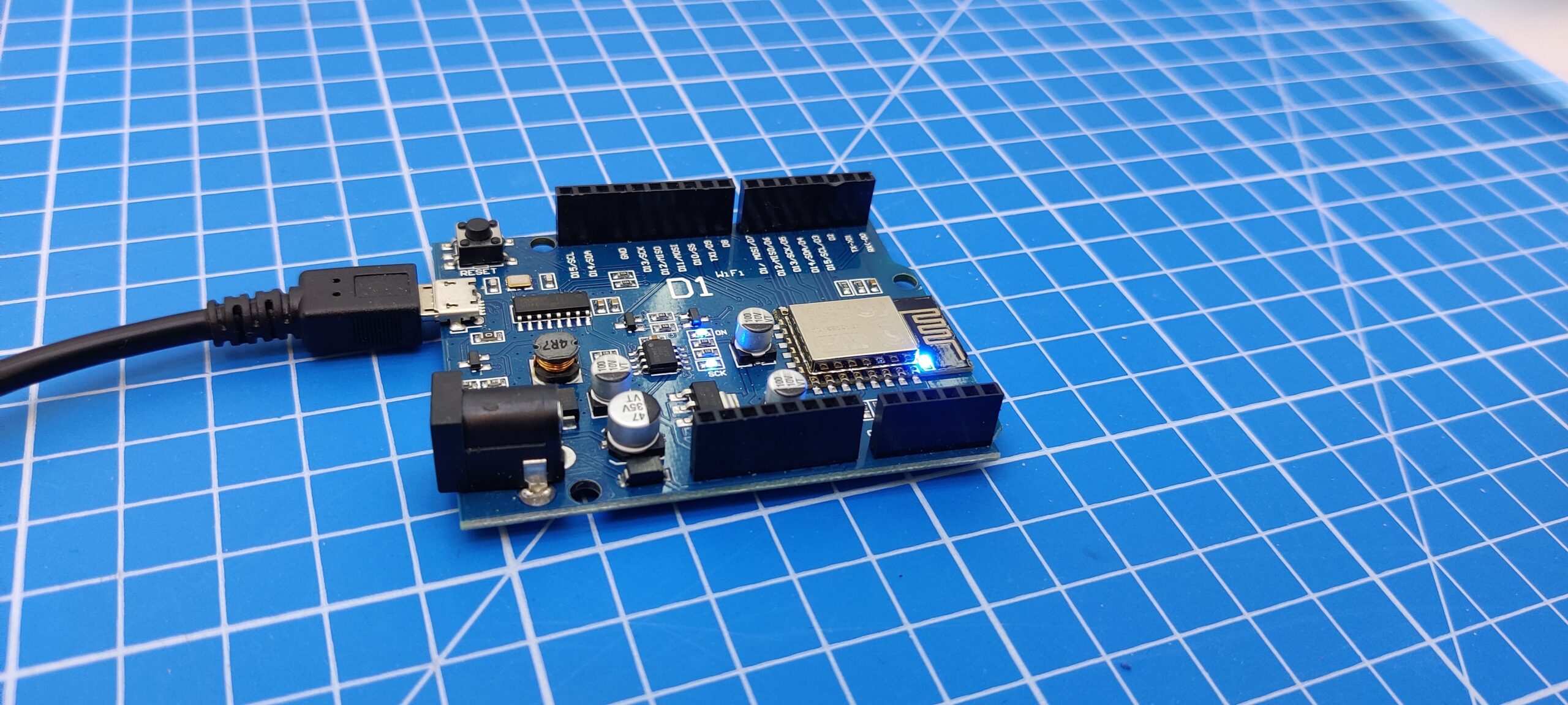
An Arduino UNO R3 looks very similar to the WeMos D1. The main difference is that the D1 has an ESP2866 WIFI module integrated on its board. This gives you the possibility to connect the D1 to the internet. Roughly speaking, the D1 is a wifi-enabled Arduino!

However, you should note that the clock frequencies of the two processors are different. The Arduino has an 8 bit Atmel processor and the D1 a Wi-Fi capable ESP8266 processor with 32 bit clock frequency. The pins of the D1 are arranged similarly to an Arduino UNO, but differ in the operating voltage. On an Arduino UNO the voltage of the pins is 5V and on the D1 it is 3.3V. However, there is also a 5V output on the D1. Because of the voltage differences on the pins you should not blindly plug an Arduino Shield on a D1. It is recommended to check the compatibility first!

In addition, it should be noted that the D1, unlike the Arduino, has only one analog pin and additionally the number of digital pins is different. The Arduino has 20 digital pins and the D1 only 16 digital pins. However, the digital pins of the D1 have more useful additional functions.
Please note: The designation of the D1 digital pins is also different from those of the Arduino and therefore must be adjusted in software.
Last but not least, the USB connector is also different. In contrast to the Arduino, the D1 has the much more common Micro USB standard.

Setup of the D1
Open the Arduino IDE and connect the D1 to the computer. Select the appropriate COM port of the D1 under Tools > Port. If the D1 is not recognized here, this is probably due to a missing driver.
If you now select the appropriate COM port and upload an example sketch to the D1 you will probably get the following error message: “An error occurred while uploading the sketch avrdude: stk500_getsync() attempt 1 of 10: not in sync: resp=0x2e”. The reason for this error is that the wrong board was selected. The name of the selected board appears in the lower right corner of the IDE:

To be able to select the D1 the board manager for the ESP8266 must be added. Insert the following link in Preferences > Board Manager: http://arduino.esp8266.com/stable/package_esp8266com_index.json

Then search for ESP8266 in Tools > Board > Board Manager and install the latest version:

Now select in Tools > Board > ESP8266 Boards > LOLIN (WEMOS D1 R2 &mini):

Now you can select an example project under File > Examples > 01.Basics > Blink and with a click on Upload the whole thing works. The example project now lets the blue LED on the ESP8266 module blink.
Attention: This setup was unique for the first time usage and does not need to be repeated again!
Connecting WeMos D1 to the Internet
The program structure corresponds to that of a regular microcontroller as known from the Arduino. There is a setup() function, which is called only once directly at the start of the program and a loop() function, which runs in a continuous loop after the setup().
First the ESP WiFi library is needed. This is included with #include <ESP8266WiFi.h>. As soon as the ESP is powered, a Wi-Fi connection should be established. Therefore the code is written into the setup() function.
We need the serial monitor to display the current state of the connection. The baudrate can be set by the user. For the D1 I use 115200. The serial monitor can be found under Tools > Serial Monitor. In the window of the serial monitor you can set the baudrate. Please select 115200 as well. If you don’t choose the same baudrate as defined in setup(), you will only see unreadable special characters.
To connect to the Wi-Fi the simple command WiFi.beginn(“WlanName”, “WlanPasswort”) is sufficient. It can be very helpful to display the IP address of the D1. For this purpose use the command WiFi.localIP()
#include <ESP8266WiFi.h>

void setup() {
  Serial.begin(115200); //Baudrate
  Serial.println("ESP starts");

  WiFi.begin("NerdCornerWiFi","NerdCornerPassword");

  Serial.print("Connecting...");

  while(WiFi.status()!=WL_CONNECTED){ //Loop which makes a point every 500ms until the connection process has finished

    delay(500);
    Serial.print(".");
  }
  Serial.println();

  Serial.print("Connected! IP-Address: ");
  Serial.println(WiFi.localIP()); //Displaying the IP Address

}

void loop() {
  // put your main code here, to run repeatedly:

}
The D1 as web server and DNS server
After the previous steps the D1 is connected to the WiFi, but not yet accessible via a browser. So that the D1 can be controlled comfortably over the Browser one needs the #include <ESP8266WebServer.h> library. Then create a web server object with the command ESP8266WebServer server(80) and set the port 80. The server can now be started with the command server.begin(). So that the D1 can check at any time whether requests are to be processed, the server.handleClient() is written into the loop() function.
If you now enter the IP address of the D1 in a browser, from a device that is in the same WiFi, the D1 is already accessible. It is just not specified yet what should happen when the D1 is called.
You can also display predefined functions here. Initially, for example, a sentence if the link has not been defined, or a text for a custom link. It is also possible to execute own functions for certain links.
server.onNotFound([](){
  server.send(404, "text/plain", "Link was not found!");
});

server.on("/", []() {
  server.send(200, "text/plain", "Landing page!");
});

server.on("/custom", []() {
  server.send(200, "text/plain", "Just a custom route!");
  ownFunction();
});
The web server setup is now complete. Since it is usually very annoying to type the IP address of the D1 into the browser or it can change, it makes sense to assign a name to the DNS of the D1. For this again a library is used, which is included by #include <ESP8266mDNS.h>. The DNS is defined once and therefore written into the setup() function. To define the DNS name, use the method MDNS.begin(DNS Name), for example MDNS.begin(nerd-corner). Additionally MDNS.update() must be written into the loop function.
#include <ESP8266WiFi.h>
#include <ESP8266WebServer.h>
#include <ESP8266mDNS.h>

ESP8266WebServer server(80);

void setup() {
  Serial.begin(115200); //Baudrate
  Serial.println("ESP starts");

  WiFi.begin("NerdCornerWiFi","NerdCornerPassword");

  Serial.print("Connecting...");

  while(WiFi.status()!=WL_CONNECTED){ //Loop which makes a point every 500ms until the connection process has finished

    delay(500);
    Serial.print(".");
  }
  Serial.println();

  Serial.print("Connected! IP-Address: ");
  Serial.println(WiFi.localIP()); //Displaying the IP Address

  if (MDNS.begin("nerd-corner")) {
    Serial.println("DNS started, available with: ");
    Serial.println("http://nerd-corner.local/");
  }

  server.onNotFound([](){
    server.send(404, "text/plain", "Link was not found!");
  });

  server.on("/", []() {
    server.send(200, "text/plain", "Landing page!");
  });

  server.on("/custom", []() {
    server.send(200, "text/plain", "Just a custom route!");
    ownFunction();
  });

  server.begin();

}

void loop() {
  server.handleClient();
  MDNS.update();

}

void ownFunction(){ //go to "IP-Adress/custom" to call this function
  Serial.println("Own function was called");

}
Afterwards you can enter http://nerd-corner.local in the browser and you will reach the D1. Please note that the ending must always be “.local”! Some Android devices do not support mDNS, then the actual IP address must still be specified. Now you can use it for your own projects!

Example program to switch the OnBoard LED on and off
At the end of this blogpost we have a simple example program where we apply what we have learned so far. We write two additional functions. One to switch on the built-in LED and one to switch it off. A small hint, in contrast to the Arduino the LED is switched on with digitalWrite(LED_BUILTIN, LOW) instead of switched off, so exactly inverted!
The functions can be called via http://nerd-corner.local/on and http://nerd-corner.local/off. Here is the complete program code:
#include <ESP8266WiFi.h>
#include <ESP8266WebServer.h>
#include <ESP8266mDNS.h>

ESP8266WebServer server(80);

void setup() {
  Serial.begin(115200); //Baudrate
  Serial.println("ESP starts");

  WiFi.begin("NerdCornerWiFi","NerdCornerPassword");

  Serial.print("Connecting...");

  while(WiFi.status()!=WL_CONNECTED){ //Loop which makes a point every 500ms until the connection process has finished

    delay(500);
    Serial.print(".");
  }
  Serial.println();

  Serial.print("Connected! IP-Address: ");
  Serial.println(WiFi.localIP()); //Displaying the IP Address

  if (MDNS.begin("nerd-corner")) {
    Serial.println("DNS started, available with: ");
    Serial.println("http://nerd-corner.local/");
  }

  server.onNotFound([](){
    server.send(404, "text/plain", "Link was not found!");
  });

  server.on("/", []() {
    server.send(200, "text/plain", "Landing page!");
  });

  server.on("/on", []() {
    server.send(200, "text/plain", "Switching LED on!");
    switchLedOn();
  });

  server.on("/off", []() {
    server.send(200, "text/plain", "Switching LED off!");
    switchLedOff();
  });

  server.begin();


  // initialize digital pin LED_BUILTIN as an output.
  pinMode(LED_BUILTIN, OUTPUT);
}

void loop() {
  server.handleClient();
  MDNS.update();

}

void switchLedOff(){
  digitalWrite(LED_BUILTIN, HIGH);   // turn the D1 LED off
}

void switchLedOn(){
  digitalWrite(LED_BUILTIN, LOW);    // turn the LED on
}


One thought on “WeMos D1 R2 setup and wifi integration”