

A cupboard that should always be locked and five people who need to access it – a classic challenge. The obvious solutions? Five keys in circulation or a single person who manages the key so that you have to borrow it every time. But we’ve all been there: the key ends up lying in the cupboard, under the carpet or behind the flower pot.
But wouldn’t it be much more practical to do away with physical keys altogether? Nowadays, there are numerous ways to open a lock: Fingerprint scanners, facial recognition, NFC, numeric codes, dials – or, of course, brute force methods such as explosives and brute force. But if you are looking for an inexpensive, non-violent and simple solution, the keypad lock comes into focus.
Surprisingly, there are hardly any really good DIY solutions for hobbyists on the Internet. So I tackle it myself – my first keypad lock, which I simply call “Version 1”.
This might also be interesting for you: Do it yourself powerbank with voltage regulator and voltmeter
Construction of the housing
The initial focus is on the housing and the keypad holder. The first question that always arises is: How big should it be? The answer depends on several factors:
- Which components are required? Each component takes up space and influences the design.
- How much space do the components take up? A compact design is advantageous, but must not restrict functionality.
- What are the haptics and operability like? The keypad should be comfortable to use without being too cramped or impractical.
These considerations form the basis for the housing design – because good planning saves time and nerves later on.
What will be inside the housing?
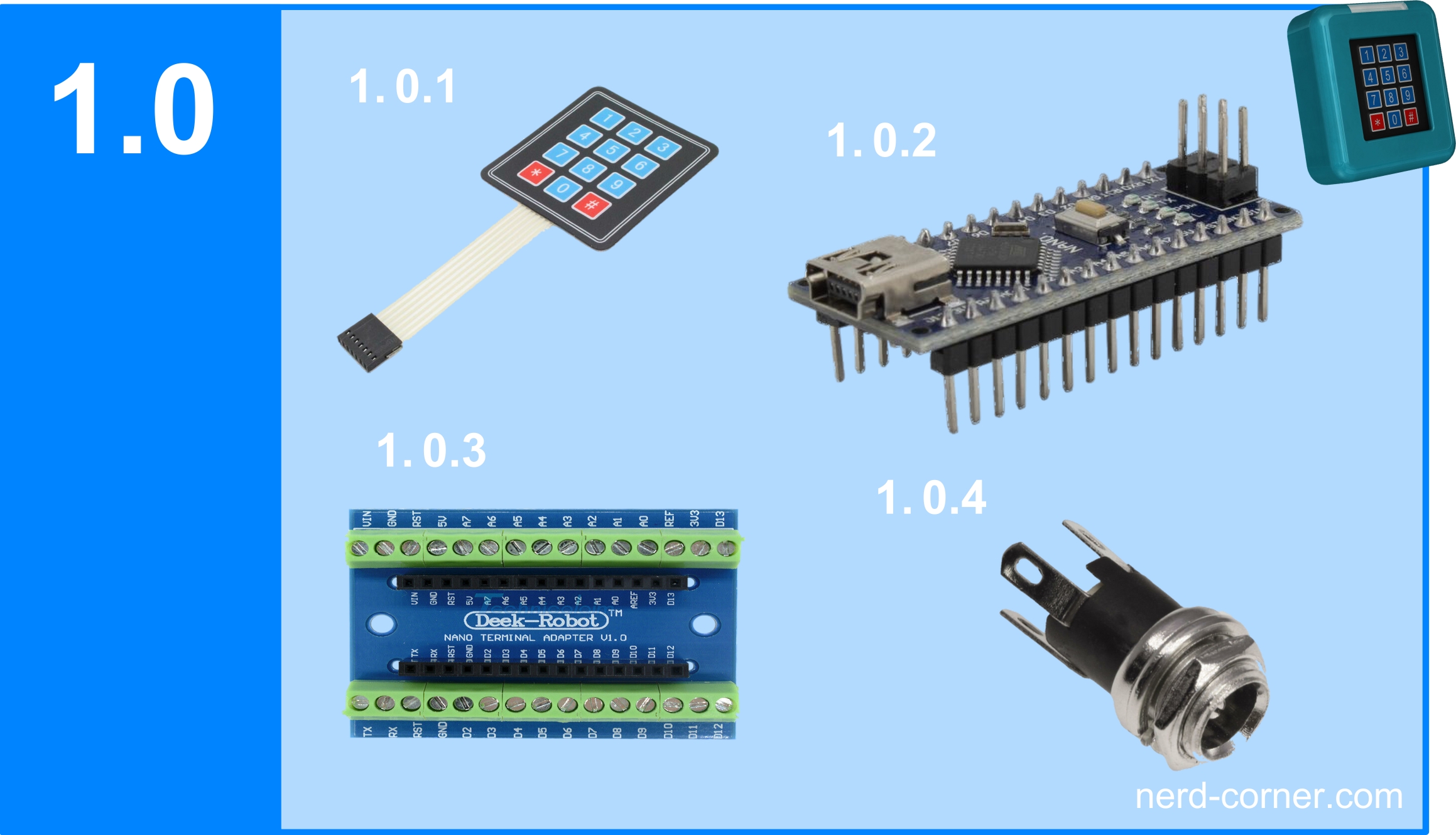
The central component is, of course, the membrane keypad (1.0.1). It has the following dimensions:
- Width: 69 mm
- Length: 76 mm
- Thickness: 0.6 mm (or 0.95 mm above the keys)
The keypad also has a ribbon cable with DuPont sockets for connection to a microcontroller. The cable itself is 85 mm long and 17.78 mm wide.
The control center of the lock is the Nano (1.0.2). To accommodate it neatly in the housing and to make the cable connections as convenient as possible, I opted for a Nano expansion board with screw terminals (1.0.4).
A hollow socket (5.5 x 2.1 mm, 1.0.4) is used for the emergency power supply so that the lock continues to function even in the event of a power failure.
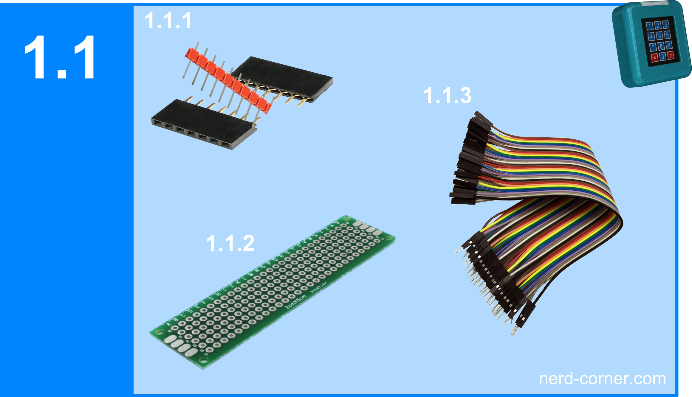
The pin and socket connectors (1.1.1) serve as the central power distribution and are later soldered to the breadboard (1.1.2). Jumper cables (1.1.3) are used to ensure that all components are reliably connected. Depending on the position of the components, different lengths are required – in this case 10 cm and 20 cm.
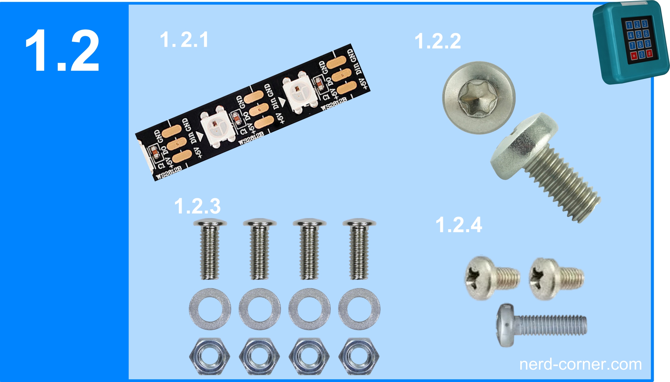
For the status display of the keypad lock, I use Neo Pixel addressable LEDs of type WS2812b (1.2.1). These can be used to control different colors and effects to visually display the current status of the lock.
I will go into the positioning of the screws in more detail later.
Now that the components have been determined, I can think about the size of the housing. This is not only determined by the installed elements, but above all by the usability and feel.
We encounter keypads every day – on ATMs, telephones, door lock systems and, of course, smartphones. The decision for the depth of the housing is based on a positive memory of my penultimate workplace: the keypad lock at the entrance was raised and easily accessible from both sides. You could operate it comfortably with your right or left thumb, and the rounded corners provided a pleasant feel when you put your hand on it.
Keypad lock Housing design
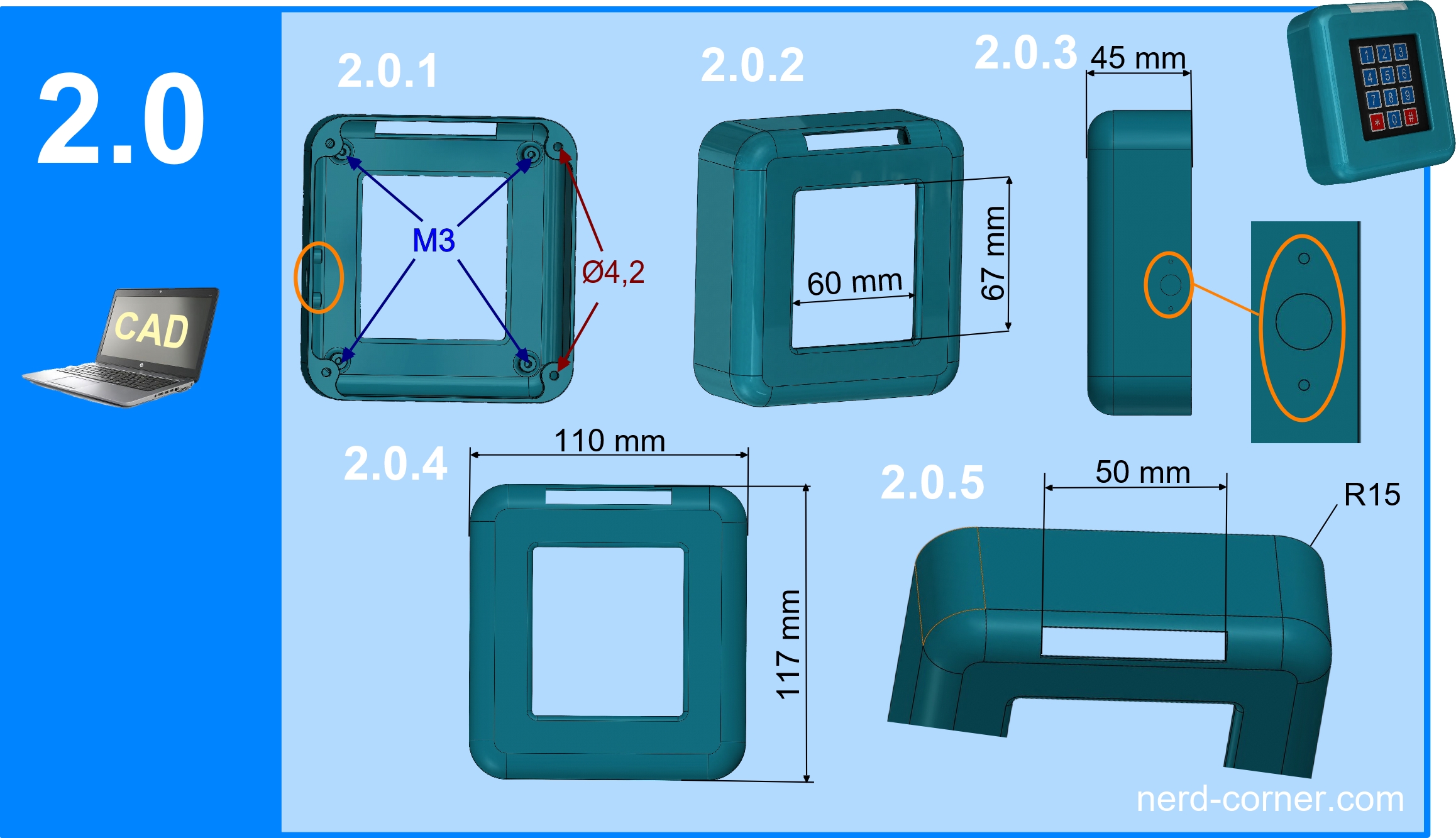
This results in a depth of 45 mm (2.0.3). For better ergonomics, the corners have a radius of 15 mm (R15) and the surrounding upper edges have a radius of 10 mm (R10). I am aware that these roundings slightly reduce the interior space, but the comfort and appearance outweigh this disadvantage.
The width and height of the housing are determined by the components to be installed. The space for the cabling must also be taken into account. Particularly important: When installed, the Nano should still be accessible with a standard USB mini cable, for example to be able to install new programs.
Mounting and fastening
- Four M3 threads (2.0.1) on the inside allow the support plate to be screwed on.
- In addition, there are four mounting points with Ø4.2 mm holes for attaching the housing to a door, cover or wall.
- The housing has a window (2.0.2) measuring 60 × 67 mm, which is intended for the keypad. This is later filled with the carrier plate.
- Retaining columns with M2 threads and the opening for the hollow socket (1.0.4) are marked with orange ellipses (2.0.1, 2.0.3).
- The next picture (2.0.4) shows the external dimensions: 110 mm wide and 117 mm high.
- In addition, an aperture or slot 50 mm long is required for the LED cover (2.0.5).
For the wall thickness of the housing, I have provided 2 mm throughout – stable enough for the intended purpose.
With the housing construction completed, we can now continue with the other components.
The support plate – the central mounting element
The next important component is the carrier plate. The name is self-explanatory: With the exception of the hollow bushing, all components are attached here. This system offers several advantages over direct mounting in the housing:
✅ Easy mounting outside the housing – More space and better handling when wiring.
✅ Modularity – different carrier plates with different components are possible.
✅ Simple enclosure design – The enclosure design remains simpler and more flexible.
✅ Easy replacement – Components can be replaced or extended more easily.
But there is another decisive advantage for the keypad lock in particular:
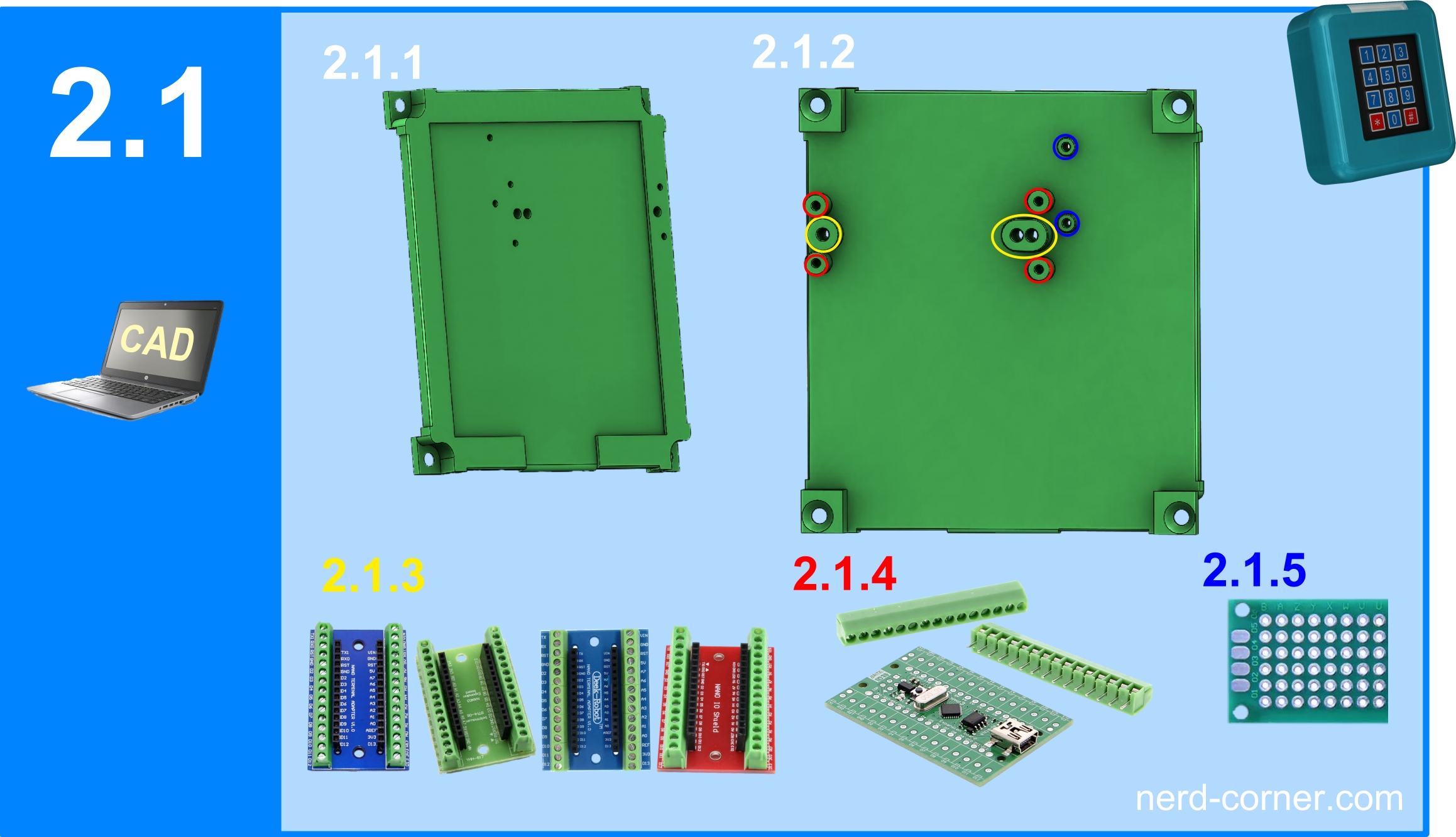
The keypad is glued directly into a designated recess in the carrier plate (2.1.1). The carrier plate and keypad are then inserted into the housing from behind and fixed in place with M3 screws. The frame of the window in the housing completely covers the edge and the cables.
🔒 Safety aspect: The window is dimensioned in such a way that the edge and the cables remain concealed, but the buttons are fully visible and operable. This means that the keypad cannot be removed without destroying it – an important protective mechanism against tampering.
Fastening the components to the carrier plate
There are various mounting options for the electronics on the back (2.1.2) of the carrier plate:
🟡 M3 thread for the nano adapter (2.1.3) – As nano adapters on the Internet often have different hole spacings, there is an additional fastening thread on the right-hand side (2.1.2) for flexible adjustment. If the holes still do not fit exactly, they can be carefully widened – but without damaging the adapter’s conductor tracks.
🔴 M2 thread for the Nano R3 ATMEGA168P (2.1.4) – An alternative, cost-effective solution instead of a Nano R3 with adapter.
🔵 M2 thread for the breadboard (20×80 mm, 1.1.2, 2.1.5) – This is used for power distribution and connects all power supply lines neatly at a central point.
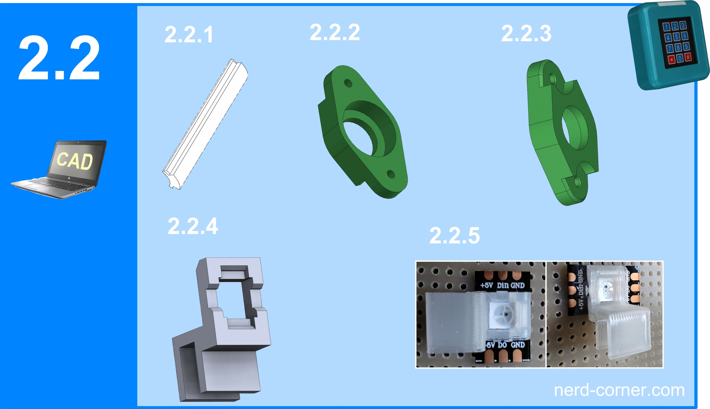
The LED cover and its attachment
The LED cover (2.2.1) has been designed so that it is clicked into the slot (2.0.5) of the housing from the rear. The radius on the outside of the LED cover corresponds to the housing radius, creating a smooth transition and allowing the cover to blend in seamlessly.
I don’t need to redesign the mounting bridge (front 2.2.2, back 2.2.3) as I have already used it successfully in other projects.
Mounting the LEDs
Now it remains to mount the three WS2812b LEDs (1.2.1). I will explain why exactly three LEDs are needed later in the programming section of this article.
The development of the LED holder (SMD50, 2.2.4) was more complex than expected. Of course, you could simply glue, clamp or hot glue the LED strips – but that seemed too unprofessional to me.
I therefore invested a lot of time and effort in designing a perfect holder. The result can be seen in picture 2.2.5.
📌 Further information:
For details on the construction, there is a separate article on NerdCorner.
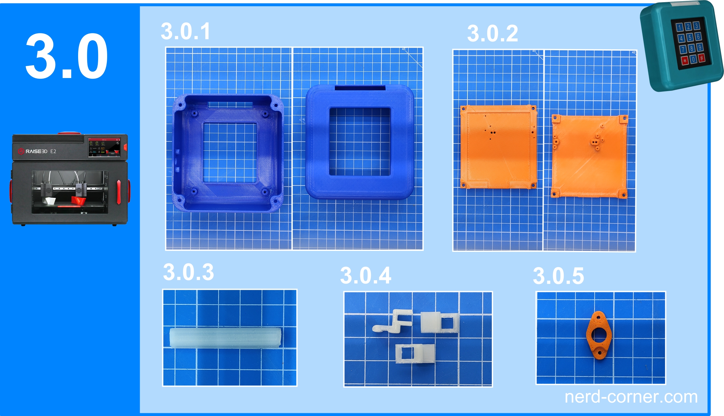
3D printing of the components
Once the design has been completed, the parts must now be printed.
📌 Material selection for the individual components:
- Housing (3.0.1): Printed with ABS filament, consisting of front and back.
- Carrier plate (3.0.2): made from PLA filament.
- LED cover (3.0.3): produced upright in the printer, printed with PLA+ in the color “natural”.
- LED terminals (3.0.4): also made of PLA+, manufactured in the same process as the LED cover.
- Bridge for the hollow socket: printed from PLA filament, analogous to the carrier plate.
With these materials, the mechanical and thermal properties of the components are optimally matched to their respective applications.
Post-processing of the components
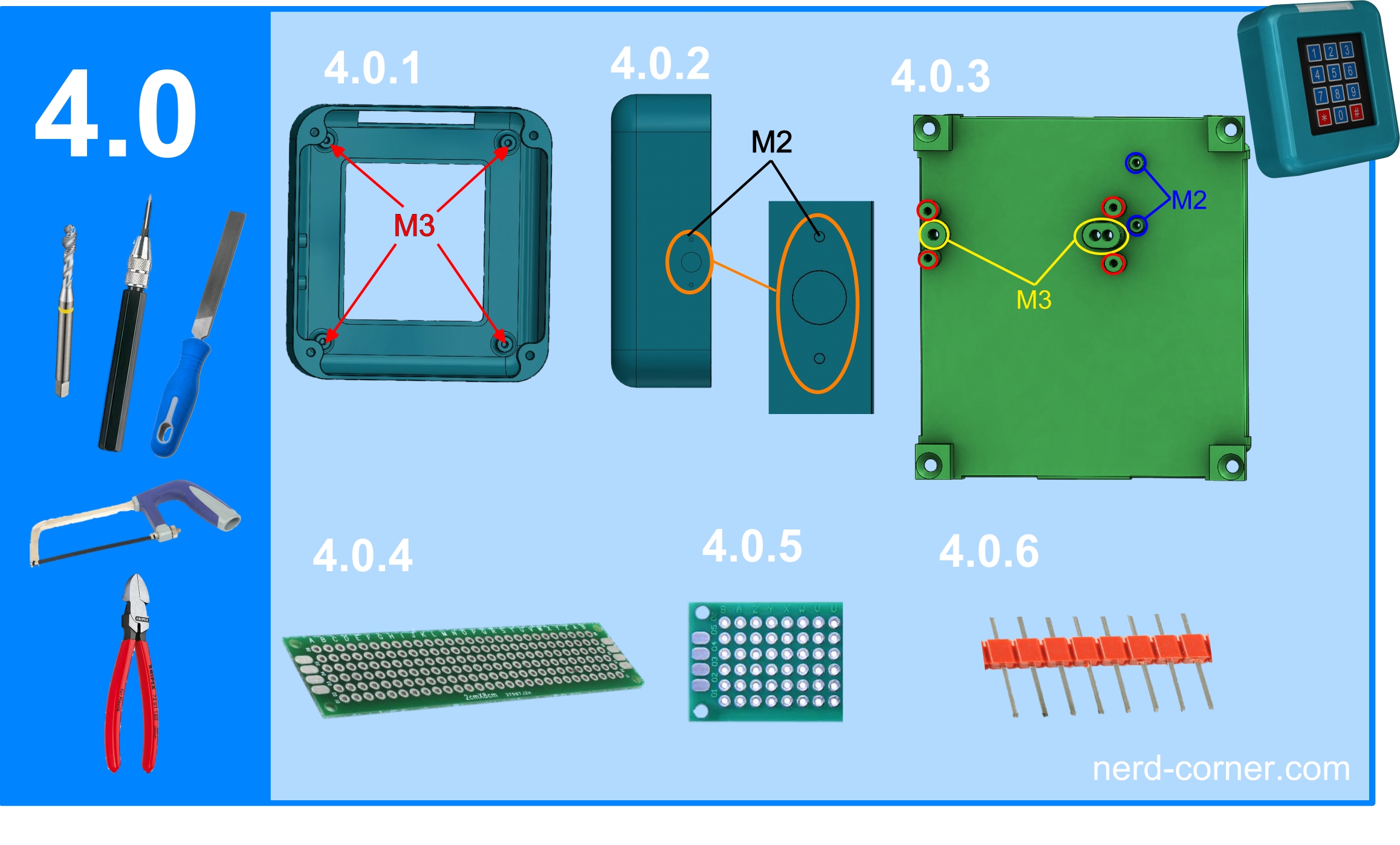
After printing, both the printed parts and some purchased parts need to be processed.
1️⃣ Cleaning the 3D printed parts
- Removal of support material and protruding print residues.
2️⃣ Cutting the thread
Housing (4.0.1):
- Four M3 threads (Attention: blind holes! Proceed carefully when cutting so as not to push the base outwards).
- Two M2 threads (4.0.2).
- Support plate (4.0.3):
- The M2 threads marked in blue must be cut in any case.
- When using a nano adapter with screw terminals (2.1.4), the M2 threads marked in red must also be cut.
3️⃣ Shortening the perforated grid plate
- The perforated grid plate (4.0.4) must be shortened to 8 to a maximum of 10 perforated grids.
Important: The mounting holes should be retained (see 4.0.5).
4️⃣ Shortening the pin header
- Shorten the pin header to eight pins using a side cutter (4.0.6).
Soldering the components
Now it’s time to solder the parts. First we concentrate on the power supply board:
1️⃣ Soldering the power supply board
- Perforated grid plate (4.0.5): Soldering the base strip (1.1.1) and the pin strip (4.0.6).
- Pin strip (4.1.2): A two-row pin and skirting board is soldered on. We connect the two rows on the back with solder.
- The rows differ in male and female as well as in the colors: red for plus and black for minus. This makes it easier to connect the power supply.
2️⃣ Soldering the WS2812B LEDs
- Soldering the connections of the WS2812B LED strip (4.1.3).
3️⃣ Soldering the hollow socket
- Finally, the hollow socket (1.0.4) is soldered (4.1.4).
- Detailed instructions on soldering the hollow socket can be found in a separate article. It is important to know the exact procedure in order to avoid mistakes.

Assembling the keypad lock
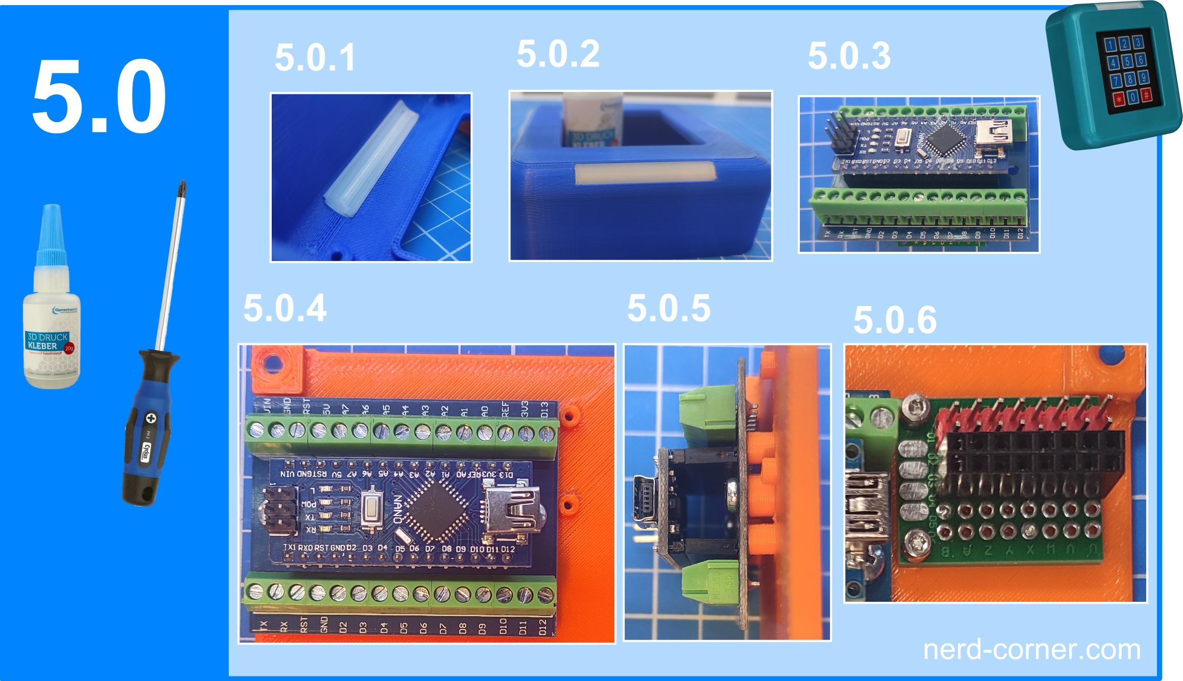
1️⃣ Installing the LED cover
- First click the LED cover (2.2.1) into the housing.
- Glue the LED cover in the intended places as shown in pictures 5.0.1 and 5.0.2.
2️⃣ Plug in the Nano R3
- Insert the Nano R3 (1.0.2) into the Nano adapter (5.0.3) of your choice.
3️⃣ Installing the Nano adapter
- Screw the Nano adapter (1.0.3) with the inserted Nano R3 (1.0.2) to the back of the carrier plate (4.0.3).
- Use the M3 threads on the carrier plate and the screws (1.2.2), as shown in pictures 5.0.4 and 5.0.5.
4️⃣ Attaching the power supply
- Attach the power supply (4.1.2) to the back of the carrier plate (4.0.3) using the screws (1.2.4).
- See figure 5.0.6.
Mounting the keypad on the support plate
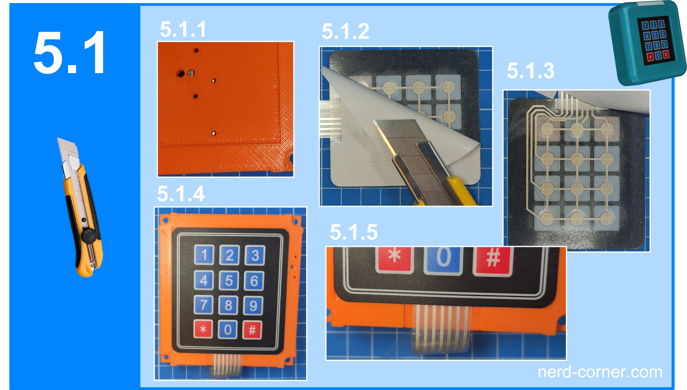
1️⃣ Selecting the screw length
- Make sure to select the correct screw length as shown in Figure 5.1.1.
- Screws must not be too long, otherwise they will protrude from the adhesive surface when the keypad is attached and the keypad cannot be glued on cleanly.
2️⃣ Preparing the keypad
- Remove the protective film from the keypad (1.0.1).
- To remove the film, use a carpet knife to carefully get between the adhesive layer and the protective film at one corner (see 5.1.2).
- Once you have reached the corner, peel off the entire protective film (see 5.1.3).
3️⃣ Stick on the keypad
- Insert the keypad (1.0.1) into the recess on the front of the carrier plate (2.1.1) and press it firmly into place.
- The keypad must be completely recessed and must not protrude over the edge (see 5.1.4).
- Make sure that the cables are also in the recess (see 5.1.5).
Wiring the keypad to the Arduino Nano R3
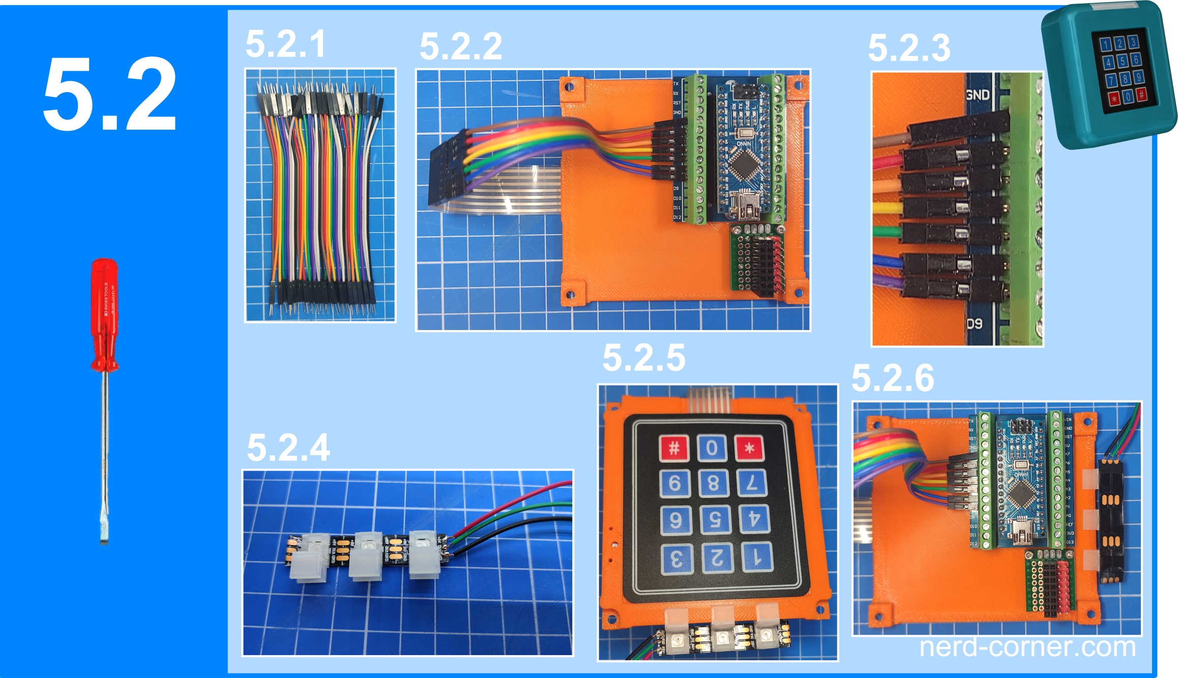
1️⃣ Using jumper cables
- Jumper cables (10 cm long, male-male) are used to connect the keypad to the Arduino Nano R3 (see 5.2.1).
2️⃣ Connecting the cables
- Make sure that you do not twist the cables, but only bend them.
- The left cable is connected to D2 of the Arduino and the right cable to D8.
- There are seven cables in total, which occupy the connections D2 to D8 (see 5.2.3).
3️⃣ Use pin headers
- As the pitch of the Arduino adapter and the keypad do not match, you can use pin strips to make the connection.
4️⃣ Fastening the LED terminals
- The clips (3.0.4) for the WS2812B LEDs are clicked onto the LEDs.
- It is best to do this on a flat surface (see 5.2.4).
5️⃣ Attaching the LED strip
- The WS2812B strip is now pushed onto the center of the top of the carrier plate (see 5.2.5 Front and 5.2.6 Rear).
Assembling the carrier plate and housing
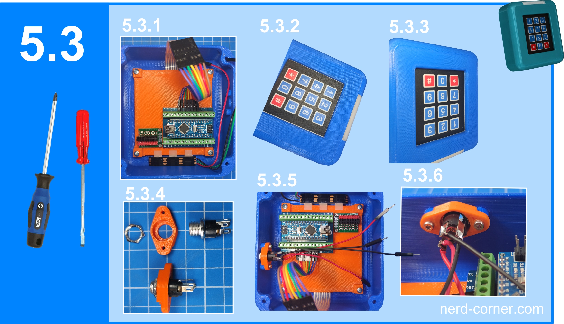
1️⃣ Screwing the support plate to the housing (5.3.1)
- Make sure that you use M3 screws that are not too long. Otherwise, they could push a bump into the front of the housing when tightened.
- The alignment of the carrier plate in the housing is important: the LED strip should be on the same side as the LED cover.
- After screwing, the keypad should be lightly pressed against the inner frame of the housing (see 5.3.2 and 5.3.3).
2️⃣ Pre-assembly of the hollow socket for the emergency power supply
- For the emergency power supply, you must pre-assemble the hollow socket and screw it to the housing.
- The hollow socket with bridge and nut is shown in Figure 5.3.4.
- Insert the hollow bush into the round recess of the bridge.
- Lock the hollow bushing with the nut on the other side of the bridge.
3️⃣ Fastening the hollow bush in the housing
- The hollow bush with the bridge is then screwed to the retaining pillars provided in the housing using M2 screws (see 5.3.5 and 5.3.6).
Connecting the cables and completing the power supply
1️⃣ Connecting the control cable for the servo motor
- The control cable for the servo motor is connected to pin D9 of the Nano R3 (5.4.1).
2️⃣ Connecting the power supply for the Nano R3
- The power supply for the Nano R3 is connected to the GND pin and the VIN pin of the Nano R3 (5.4.2).
3️⃣ Connecting the control cable for the WS2812B
- The control cable for the WS2812B LED strip is connected to pin D10 of the Nano R3 (5.4.3).
4️⃣ Wiring of the power distributor
- All remaining cables must be connected to the power distributor:
- Servo motor connection
- Arduino Nano R3
- WS2812B LED strip
- Hollow socket All connections are made with plus and minus (see 5.4.4 and 5.4.5).
5️⃣ Using different colors and connection types for the wiring
- It helps to use different cable colors:
- Red for plus
- Black for minus
- The power distributor has different connection types:
- Male for plus
- Female for minus
6️⃣ Note on the hollow socket
7️⃣ Attaching the connector housings for the servo motor and power supply
- A three-pin plug is required for the servo motor connection.
- A two-pin plug is required for the external power supply.
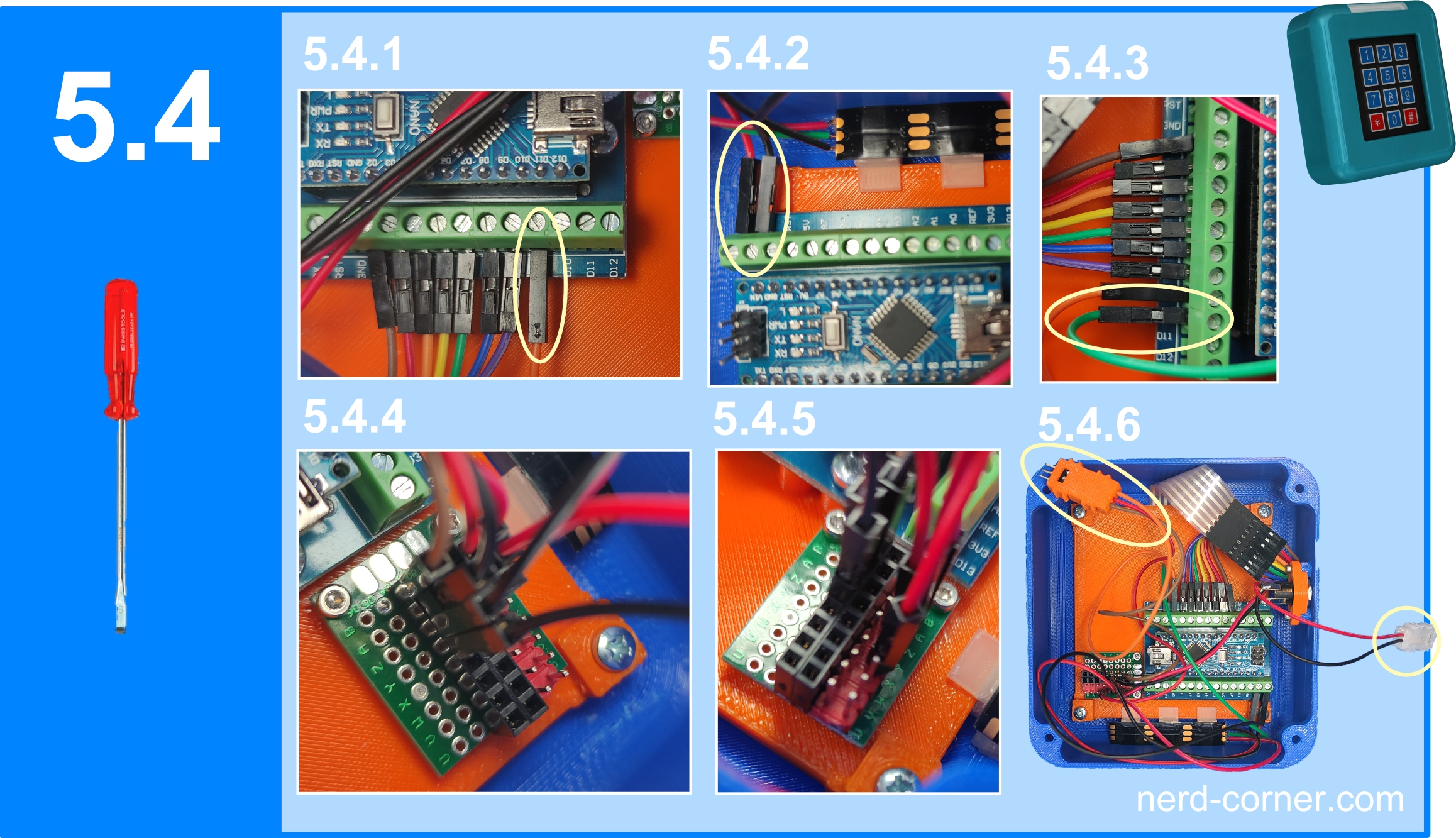
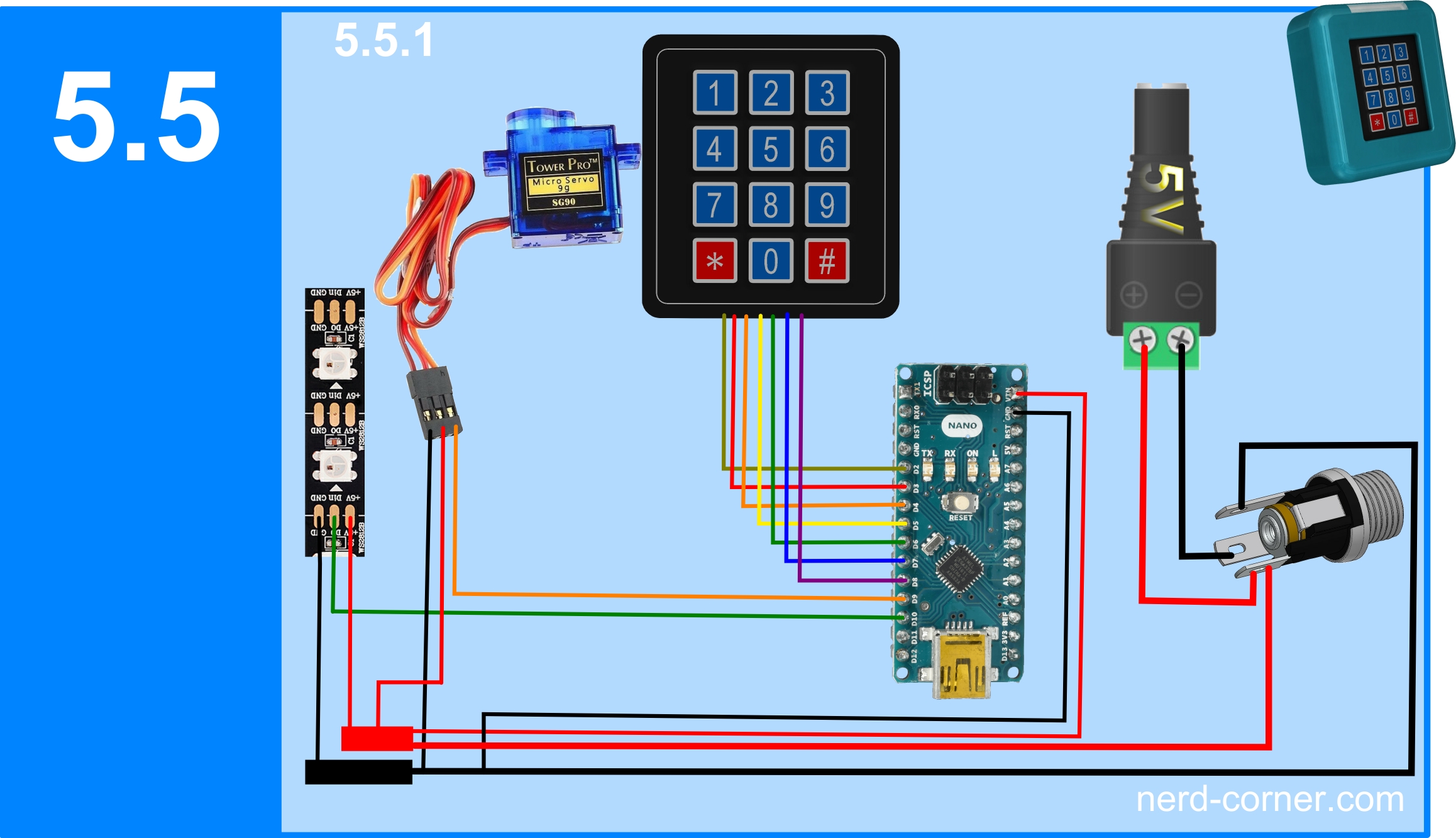
Figure 5.5.1 shows the entire cabling again.
Arduino code
After the intensive work with the hardware and the 3D printer, we now turn our attention to the strategy and programming of the keypad lock. Why is a strategy important for a keypad lock? A well thought-out sequence of actions – i.e. the order in which the keypad lock is operated, which events result from certain actions and which goal is being pursued – forms the basis for functional control. This guideline is therefore also crucial for programming the keypad lock: it determines what should happen when and which hardware is used. The aim is to create a logical and comprehensible sequence of events, which in this case can also be understood visually.
Example 1:
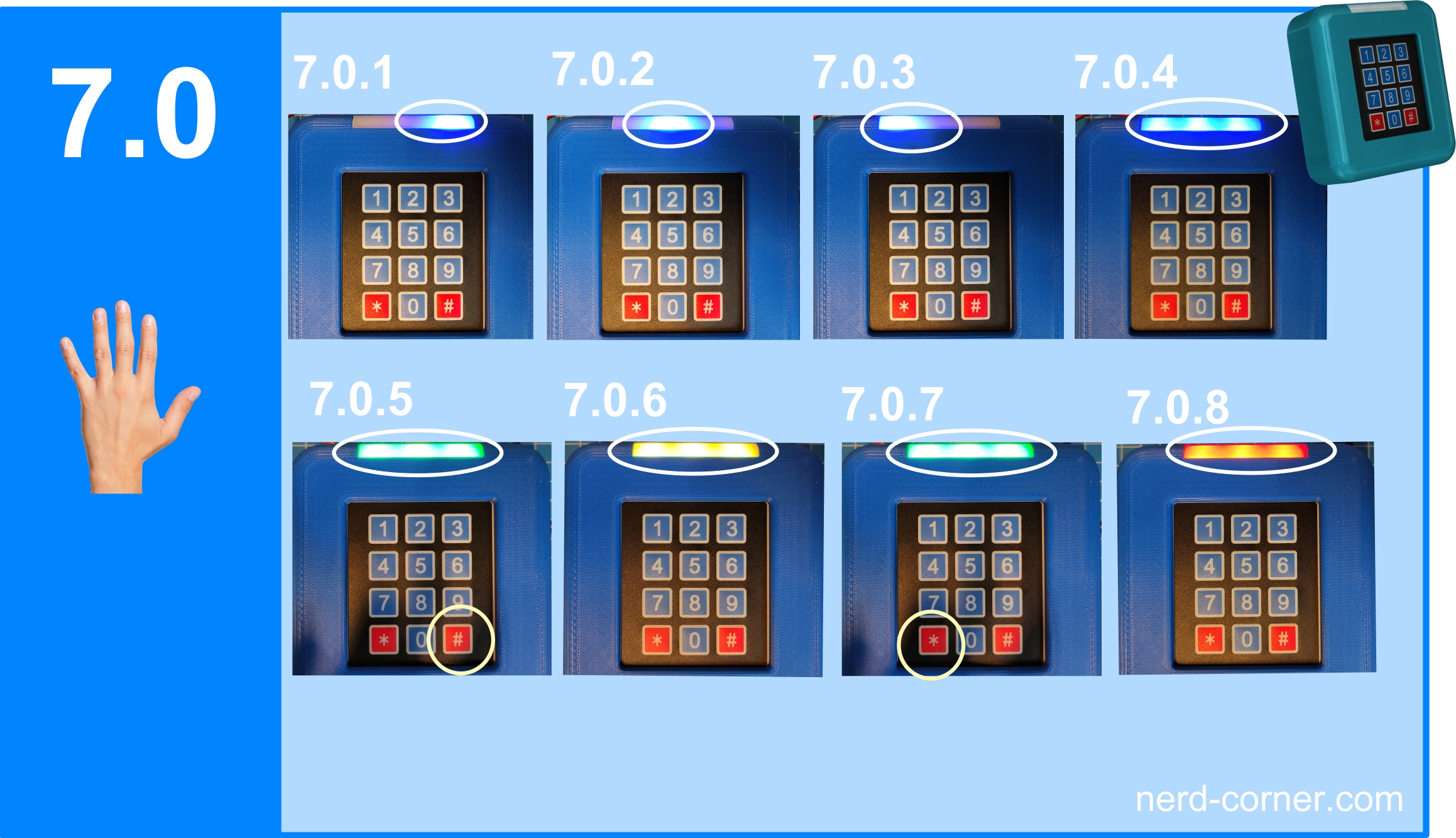
The keypad lock should display how many digits have already been entered. (See Figures 7.0.1 to 7.0.4)
Example 2:
The keypad lock should indicate whether the password entered is correct after pressing a specific key. (See figure 7.0.5)
Example 3:
The keypad lock should indicate if something has been entered incorrectly, such as an incorrect password or too many keystrokes. (See figure 7.0.8)
Example 4:
The keypad lock should display the current status. (See Figures 7.0.5 to 7.0.7)
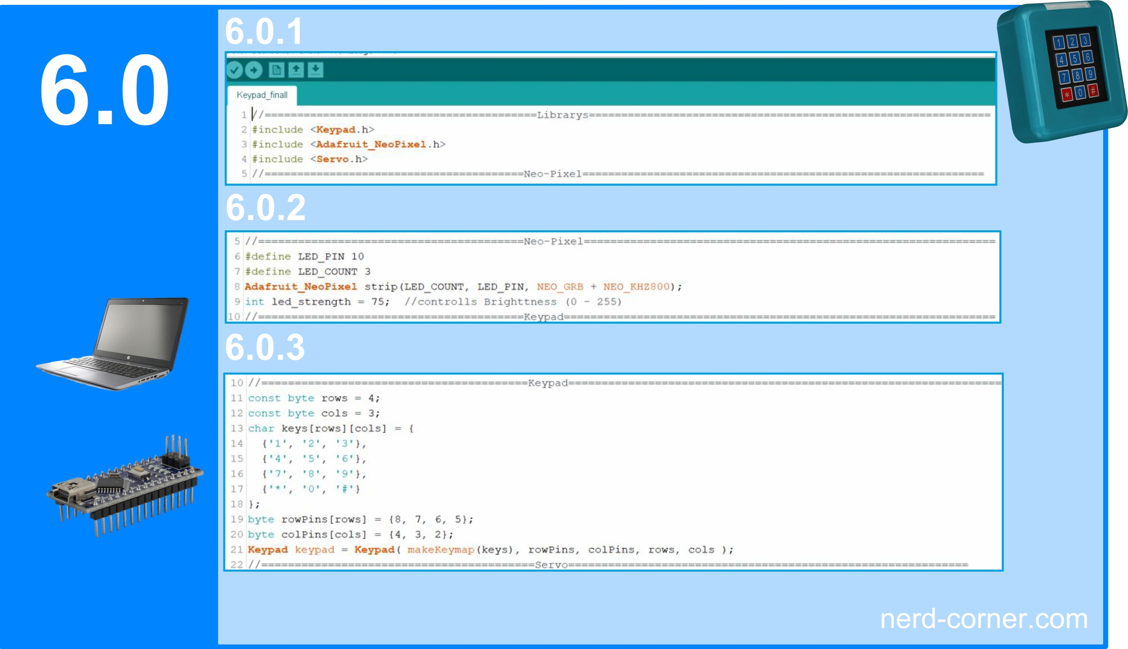
Now let’s move on to programming the keypad lock, which differs from conventional programs on the Internet in a few respects. To begin with, the three necessary libraries are included: <Keypad.h> for the keypad, <Adafruit_NeoPixel.h> for the WS2812B LEDs and <Servo.h> for the servo motor (Figure 6.0.1). In the following section, the pin assignment for the LEDs is defined, whereby pin D10 is used and the number of LEDs and the color scheme are determined. The brightness of the LEDs is also defined – this value can be adjusted depending on the location, with higher values providing more brightness (values from 0 to 255). (See figure 6.0.2) The third section is dedicated to the description of the keypad used, including the number of rows and columns and the assignment of the buttons. (See figure 6.0.3).
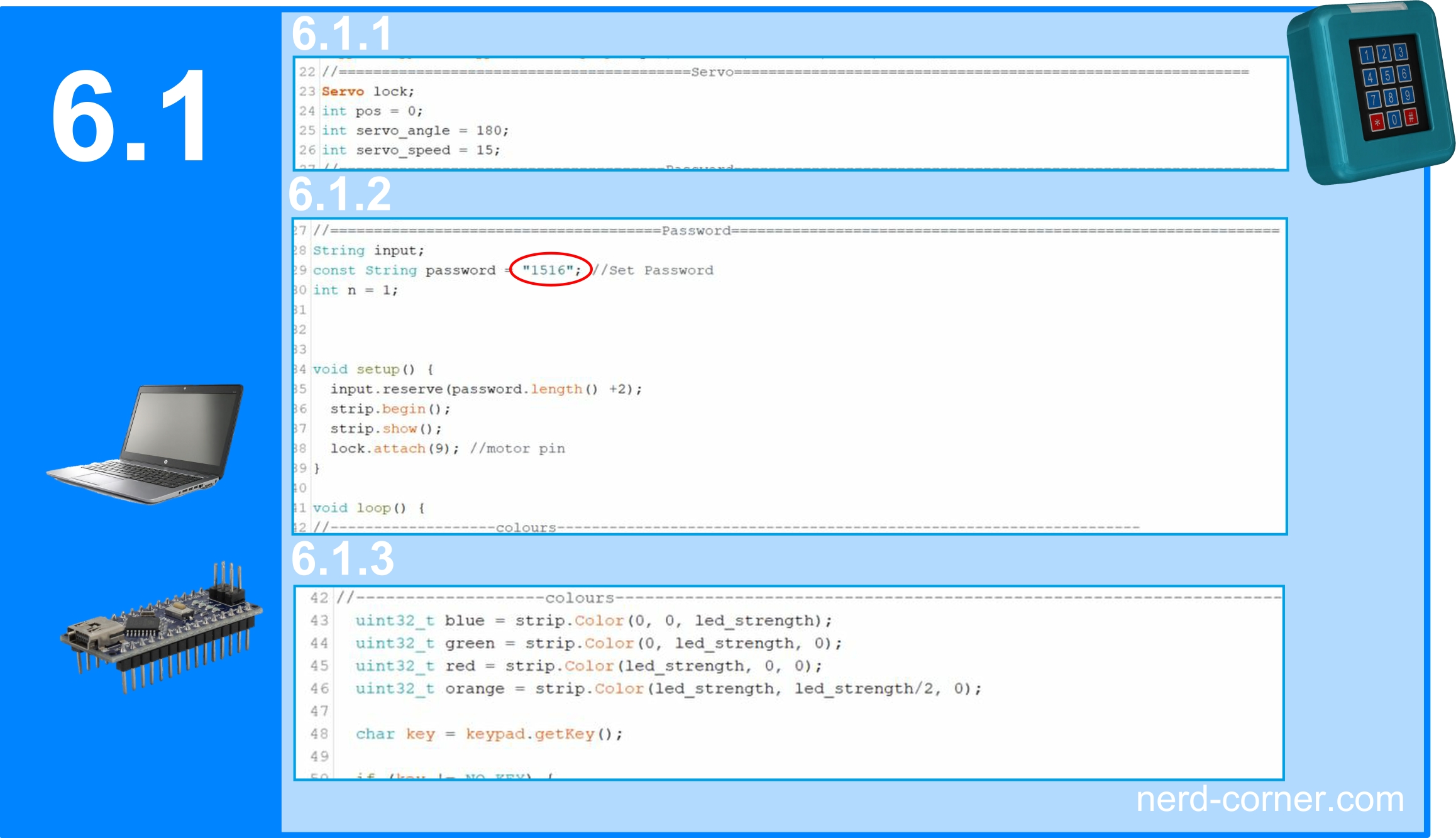
In the fourth section, the servomotor is configured by defining the degree range it can cover and the speed at which it should move (see Figure 6.1.1). This is followed by the section for entering the password. Here you have the option of changing the default password 1516 to set a new four-digit password. The program will only work correctly if a four-digit code is entered. In this section, the control pin for the servo motor is also set to D9 (see Figure 6.1.2). The following section is dedicated to defining the colors for the various events.
The last two sections explain the behavior of the keypad lock during certain actions. This description is of course only a rough overview of the program. In a future article for keypad lock version 2, we will explain the program in more detail and more comprehensively.
//==========================================Librarys==============================================================
#include <Keypad.h>
#include <Adafruit_NeoPixel.h>
#include <Servo.h>
//========================================Neo-Pixel==============================================================
#define LED_PIN 10
#define LED_COUNT 3
Adafruit_NeoPixel strip(LED_COUNT, LED_PIN, NEO_GRB + NEO_KHZ800);
int led_strength = 75; //controlls Brighttness (0 - 255)
//========================================Keypad=================================================================
const byte rows = 4;
const byte cols = 3;
char keys[rows][cols] = {
 {'1', '2', '3'},
 {'4', '5', '6'},
 {'7', '8', '9'},
 {'*', '0', '#'}
};
byte rowPins[rows] = {8, 7, 6, 5};
byte colPins[cols] = {4, 3, 2};
Keypad keypad = Keypad( makeKeymap(keys), rowPins, colPins, rows, cols );
//=========================================Servo============================================================
Servo lock;
int pos = 0;
int servo_angle = 180;
int servo_speed = 15;
//======================================Password===============================================================
String input;
const String password = "1516"; //Set Password
int n = 1;


void setup() {
 input.reserve(password.length() +2);
 strip.begin();
 strip.show();
 lock.attach(9); //motor pin
}

void loop() {
//-------------------colours-------------------------------------------------------------------
 uint32_t blue = strip.Color(0, 0, led_strength);
 uint32_t green = strip.Color(0, led_strength, 0);
 uint32_t red = strip.Color(led_strength, 0, 0);
 uint32_t orange = strip.Color(led_strength, led_strength/2, 0);

 char key = keypad.getKey();

if (key != NO_KEY) {
//-------------------------End conditions------------------------------------------------------
 if (key == '#') {
 if (input == password) {
 //unlock
 strip.clear();
 strip.fill(green, 0, LED_COUNT);
 strip.show();
 for (pos = 0; pos <= servo_angle; pos += 1) {
 lock.write(pos);
 delay(servo_speed );
 }
 while (1 == 1)
 { char key = keypad.getKey();
 strip.clear();
 strip.fill(orange, 0, LED_COUNT);
 strip.show();
 if (key == '*')
 {
 strip.clear();
 strip.fill(green, 0, LED_COUNT);
 strip.show();
 break;
 }
 }

 for (pos = servo_angle; pos >= 0; pos -= 1) {
 lock.write(pos);
 delay(servo_speed );
 }
 n = 1;
 input = "";
 delay (1000);
 strip.clear();
 strip.show();
 } else {
 //wrong password
 strip.clear();
 strip.fill(red, 0, LED_COUNT);
 strip.show();
 n = 1;
 input = "";
 delay (1000);
 strip.clear();
 strip.show();
 }
 }
 else if (n == password.length() + 1) {
 //Input too long
 strip.clear();
 strip.fill(red, 0, LED_COUNT);
 strip.show();
 n = 1;
 input = "";
 delay (1000);
 strip.clear();
 strip.show();
 }
//----------------------------------Buttons------------------------------------------
 else {
 input += key;
 if (n == password.length() ) {
 strip.clear();
 strip.fill(blue, 0, LED_COUNT);
 strip.show();
 n++;
 }
 else {

 strip.clear();
 strip.setPixelColor(n-1, blue);
 strip.show();
 n++;
 }
 }
 }

}
Function
Operating the keypad lock is very intuitive. As soon as the first button is pressed, the right-hand LED lights up blue (7.0.1). When the second button is pressed, the middle LED turns blue (7.0.2). After the third button is pressed, the left-hand LED lights up blue (7.0.3). Finally, with the fourth button, all three LEDs light up blue (7.0.4). When these three LEDs light up blue, the user knows that the # button must be pressed.
If the # button is pressed, the password is checked. If the password is correct, all three LEDs light up green at the same time and the servomotor is activated (7.0.5). The green light remains on as long as the servomotor has not yet reached its end position (open). As soon as the servomotor reaches the end position (open), the LEDs change from green to orange (7.0.6). The orange color remains until the user presses the * button.
After pressing the * button, the LEDs change back to green (7.0.7) and remain in this color until the servomotor has reached the end position (closed). If this is the case, the LEDs go out and the keypad lock is ready for new entries.
However, if the password is incorrect after pressing the # button in step 7.0.4, all three LEDs light up red (7.0.8). The red light is also displayed if more than four buttons, apart from the # button, are pressed.
Door mounting
Of course, this variant is not intended for use on an ordinary door, where you simply walk through and the door closes by itself. The reason for this is that the lock remains open until the * button is pressed. But how can you press the * button when you are on the other side of the keypad lock, behind the wall? A delay in the program could help, but who knows how long it takes to pass through the door and close it behind you? A much more sensible solution would be to implement an additional switch that is placed on the other side of the door. When pressed, this switch would lead directly to point 7.0.6 and open the lock so that the door can be opened from the inside without having to enter a password.
But that’s for the future. Now we come to mounting the keypad lock on a door. I have provided four holes on the back of the housing for this purpose. These holes have a recess on the inside for conventional hexagon nuts M4 DIN 934. The corresponding holes can be seen in Figure 8.0.1 (rear view) and Figure 8.0.2 (front view), whereby the housing is shown slightly transparent for better visualization. Installing the nuts is very simple: After ensuring that all support material has been removed, the nut is pressed into the recess provided from behind. Press-in nuts should not be used as they are unnecessarily expensive.
I have developed a drilling template for fixing to the wall or door (Fig. 8.0.3). This template contains a hole with a diameter of 4 mm at each of the four corners. The distance between the holes corresponds to the distance between the holes on the housing. The template can be easily fixed to the surface of the door, for example with adhesive tape (Fig. 8.0.4). This saves you the tedious task of marking out the drill holes and avoids errors.
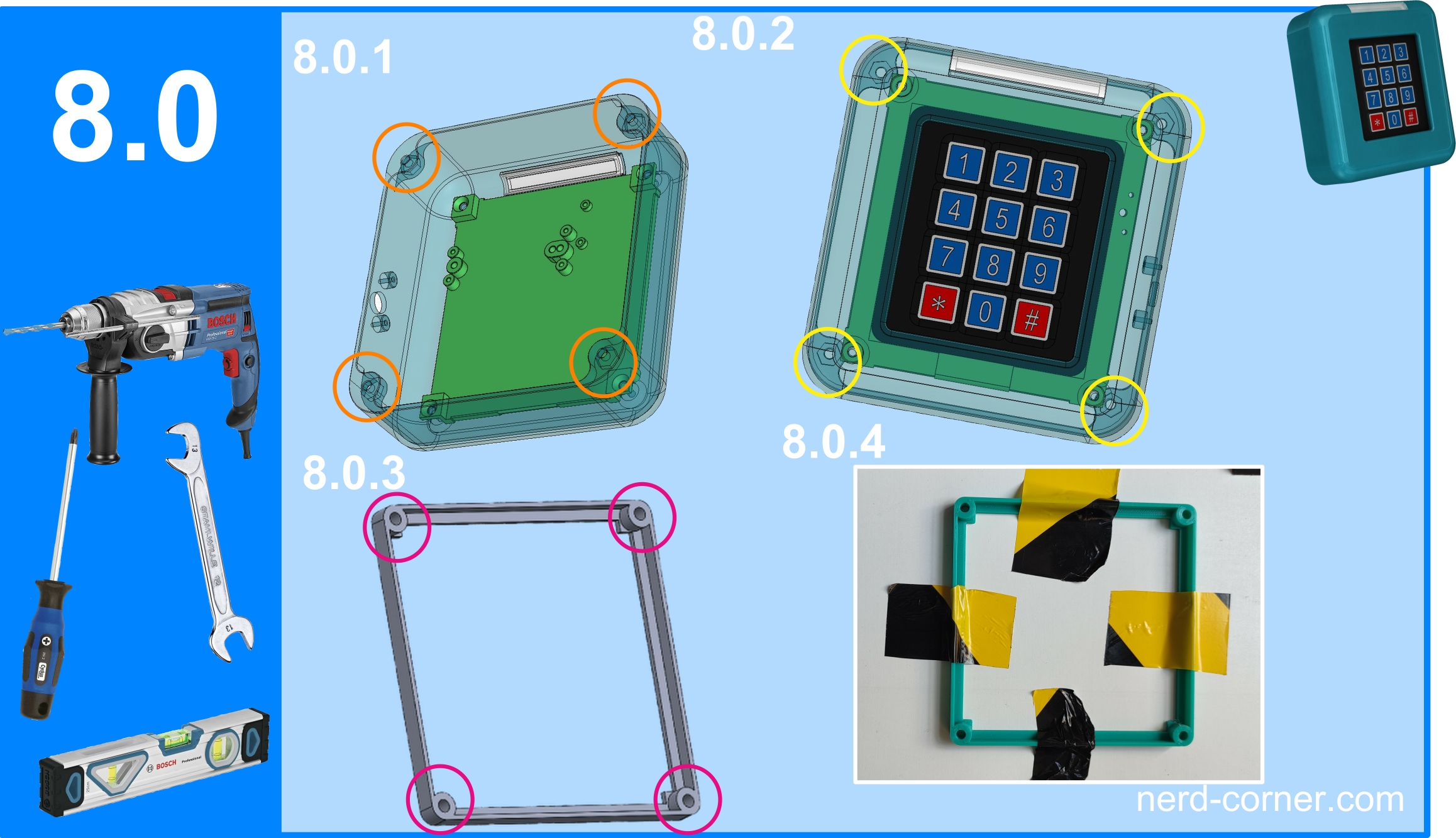
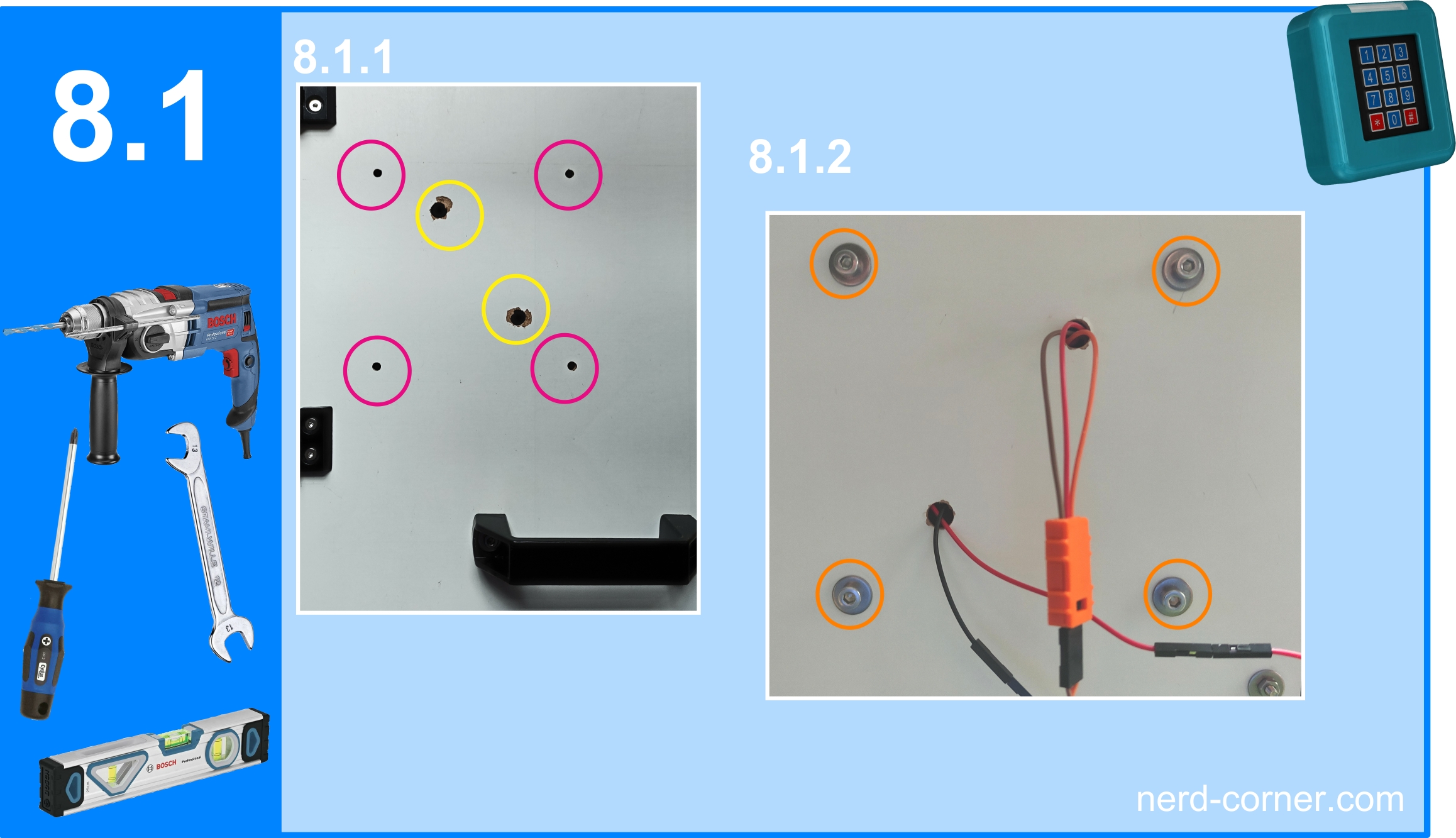
Figure 8.1.1 shows the drilled mounting holes from the front, marked by magenta-colored circles. Thanks to the drilling template, these holes are the correct distance apart. If the position slips slightly during drilling or is not exactly correct, this is not a problem. In this case, you can simply drill the mounting holes slightly larger to align the keypad lock precisely when screwing it on. In addition, two holes can be seen in yellow circles in this picture, which are unfortunately slightly broken out at the edge. These holes are intended for the servo cable and the power supply. Once the holes had been drilled, I fitted the keypad lock and fed the cables through the holes provided on the back of the door (Fig. 8.1.2).
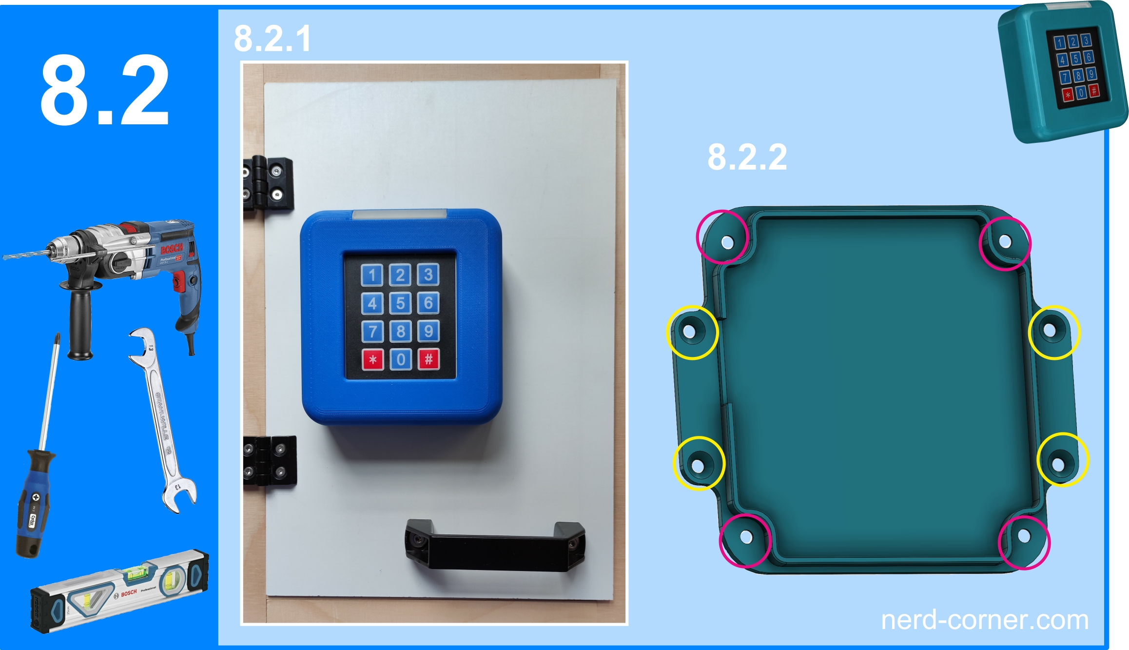
The entire assembly of the keypad lock is shown on the front side of the door in Image 8.2.1. If you are not satisfied with this mounting solution, don’t worry: As a final step, I have designed a back cover that allows the keypad lock to be mounted on a wall or frame (Image 8.2.2). To do this, simply place the housing of the keypad lock onto the back cover and secure it from behind using M4 countersunk screws (marked by magenta circles in Image 8.2.2). After that, the entire construction is mounted on the wall, for which two tabs with two holes each are available (yellow circles in Image 8.2.2).
It is also important to remember to add one or more openings in the housing for the servo and power supply cables. Additionally, the security risk should be considered, as an unauthorized person could potentially unscrew the keypad lock using the accessible screws.
Locking Mechanism
If you’re still missing a real locking mechanism that goes beyond just a servo connection, you can look forward to the “Locking Unit,” which is already in development and will be featured in future versions of the keypad lock.
The development of the keypad lock was an exciting yet challenging task. Some key features of VERSION 1 of the keypad lock are particularly noteworthy:
- Compatibility with various Arduino Nano models and adapters – Ensures flexibility in hardware selection.
- Visual feedback – Users are directly informed about number input and the status of the keypad lock.
- Emergency power supply via barrel jack – Guarantees reliable operation in case of power failures.
- Stable software – Developed to ensure reliable functionality.
- Optimized ergonomics for both left- and right-handed users – Designed for comfortable use by all users.


