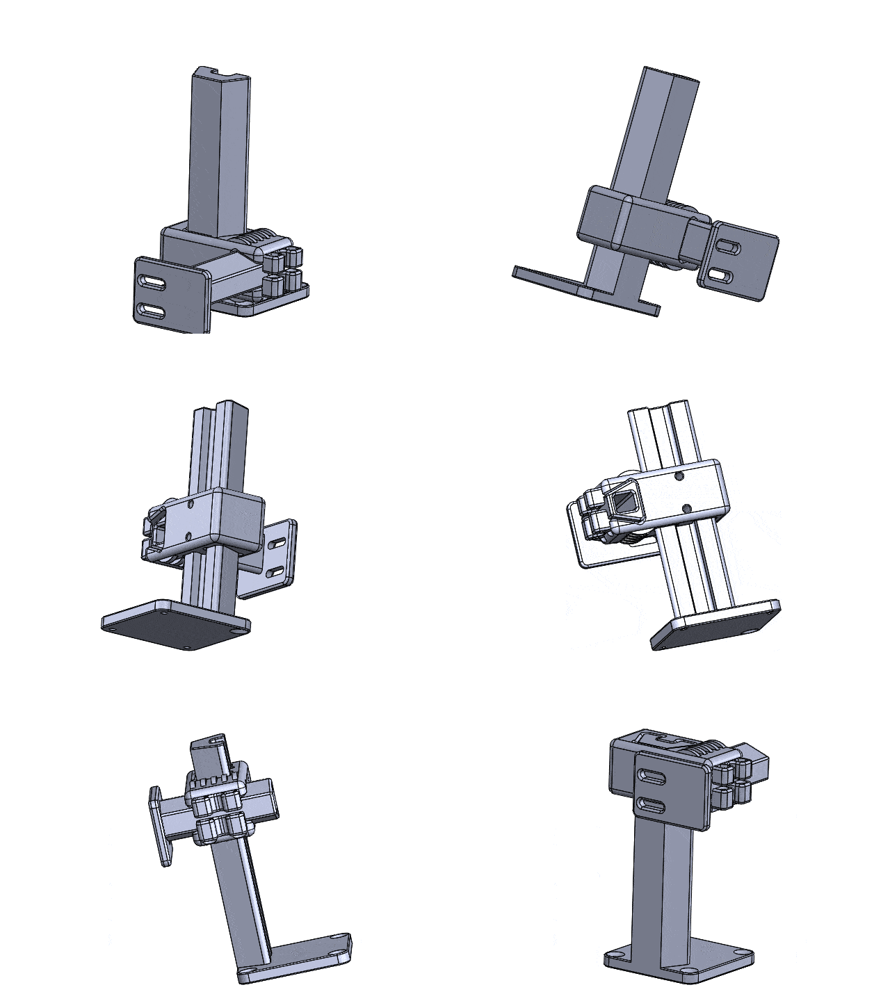
I was looking for a stand to hold an optical mouse board for measuring the path of a wheel. Unfortunately I did not find a 2 adjustable axis CAD Design for this purpose. Neither on Thingiverse nor anywhere else. So I constructed my own one. The result is a holder with 2 movable axes in Y- and Z- direction.
This might also be interesting for you: Stepper Stand Nema 17 CAD Design

List of components
- Hexagon socket screw M4x20 (2 times)
- Washer M3 (2 times)
- Insert nut M3 (2 times)
- Hexagon socket screw M3x20 (2 times)
What was the motivation?
This is a very light and stable stand that can be adjusted in two axes. It is well suited for the exact positioning of sensors or other components. I originally designed this stand to hold an optical mouse board for measuring the path of a wheel. In the course of time it turned out that this stand can do much more than originally thought. Often these stands are made of metal and plastic and the magnetic metal of Hall sensors, for example, interferes with the readout of data. In addition, many stands are too large or too heavy and have no holes to screw on.

How to construct the 2 adjustable axis CAD Design?
For the construction of the stand I decided to use a so-called dovetail guide. This dovetail guide is a classical guide variant in mechanical engineering and is still used very often today. The advantage is that a parallel guidance is forced with the two inclinations and a twisting of the carriage is prevented. With round guides two pieces are always necessary to achieve this effect.
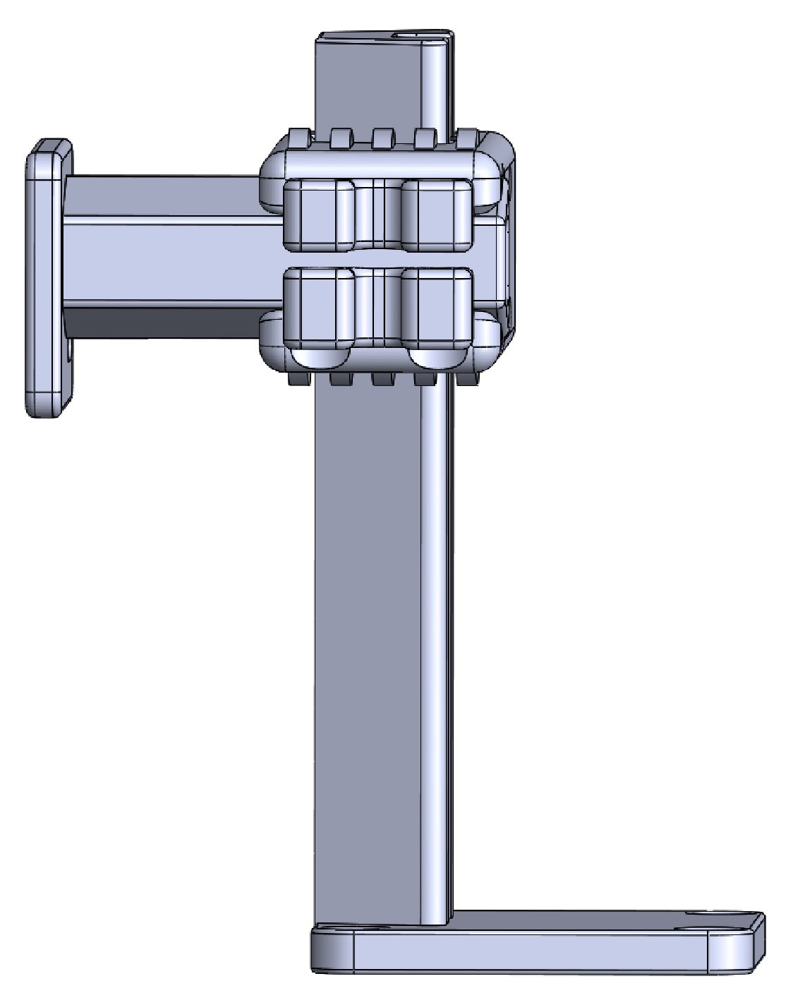
The bevels also contribute to precise positioning, because the clamping screw is attached on the other side and thus pulls the carriage towards the bevels. There are two dovetail guides for the Z-axis and Y-axis. The travel distances in the Y-axis are 23mm and in the Z-axis 75mm. For most positioning applications this is sufficient.
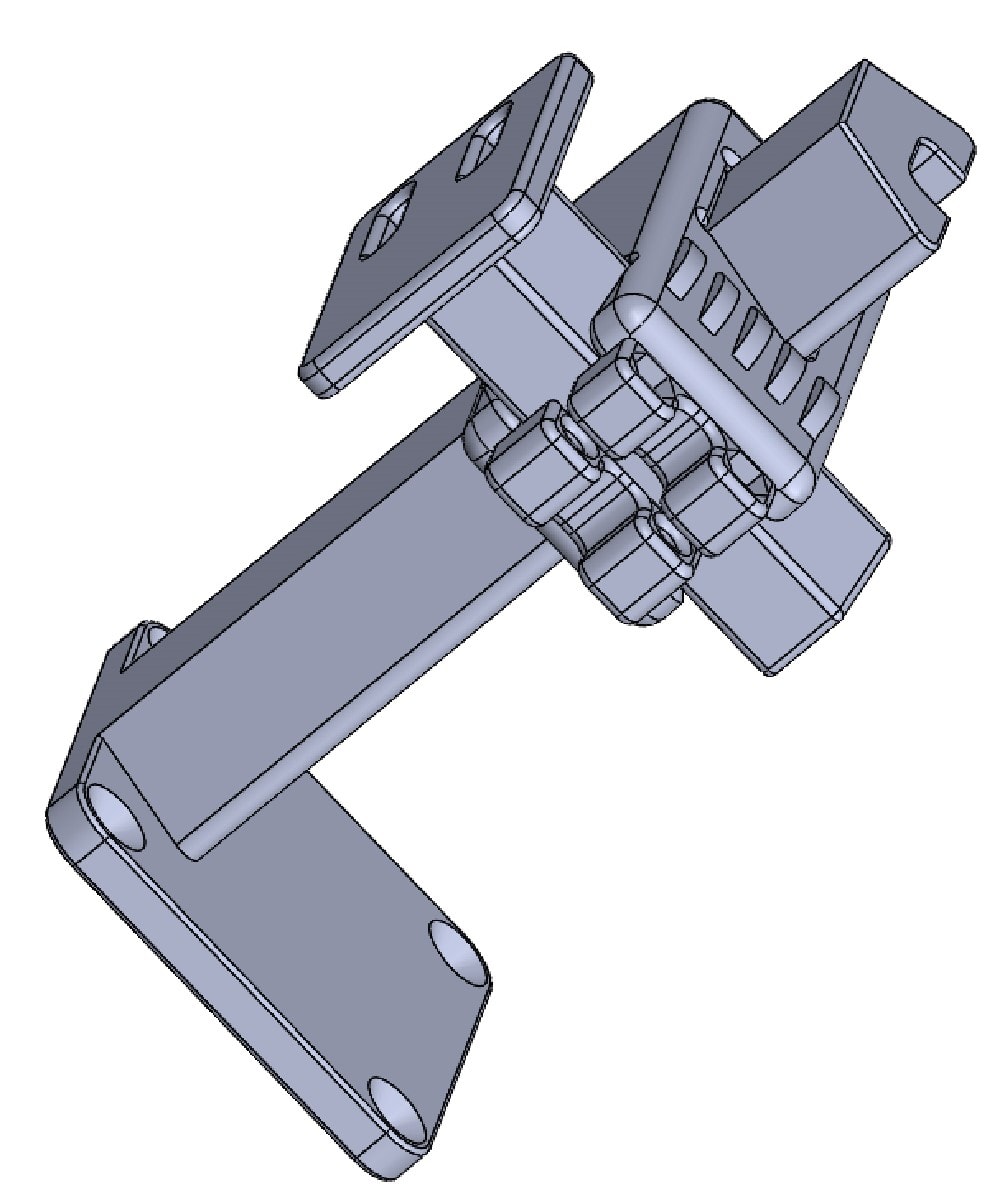
The decentralized placement of the guide column on the base plate provides more projection in the Y-axis and makes it easier to screw on the base plate. The mounting plate has two oblong holes so that sensors in the X-axis can also be easily corrected. In my case the long holes are extremely helpful for positioning the optical mouse board.
The semicircular ribs on the carriage serve to reinforce the thin wall thickness at the dovetail guide opening. This rib construction is very stable and resistant to vertical pressure. Two different locking systems are used. On the slide in the Z-axis two M4 screws drill easily into the material of the stand. This also means that only a limited number of clamps can be used because of the deformation of the material!
With the second locking there is no material removal. Instead, the material is stretched or compressed here. It remains to be seen which type is better in the long run. For the thread on the slide for the Z-axis, the thread is cut with an M4 tap. For the clamping at the Y-axis I use insert nuts for the thread. If you do not open and close the clamps a hundred times a day, it will surely last for many years!


One thought on “2 adjustable axis – CAD Design”