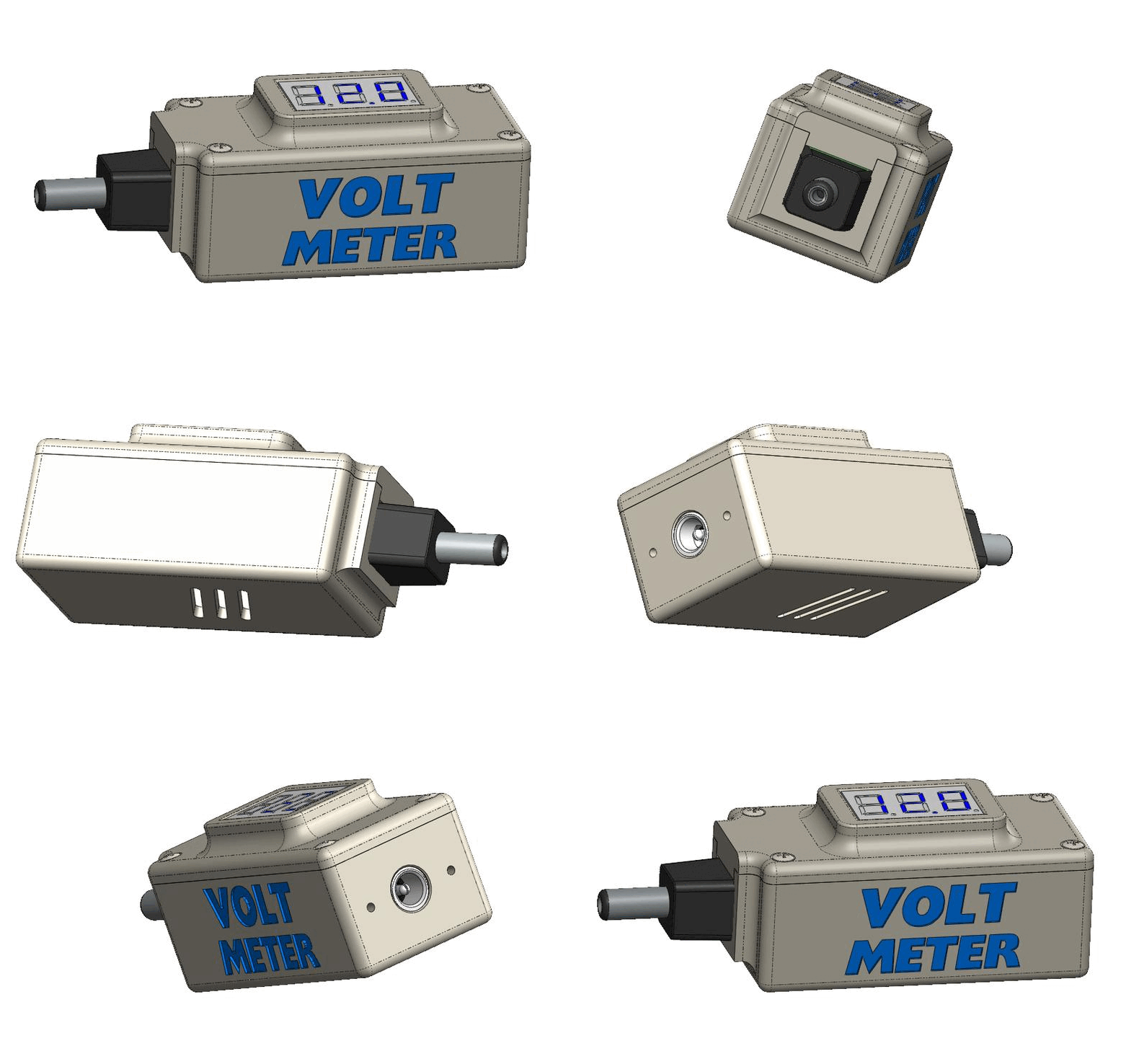
If you want to measure voltage with a voltmeter or multimeter, you normally need two hands. But usually you only have one hand free. You can of course use crocodile clips or similar to help you, but this is usually awkward. Especially in experimental setups, you often have to measure the voltage at different points to analyze the behavior of the circuit.
The solution to my problem is the mini-voltmeter, which I have used many times in various projects in the past. The accuracy of the mini-voltmeter is usually sufficient and my projects tend to be in the low-voltage range. In addition, the mini voltmeters are relatively inexpensive and you can get them everywhere.
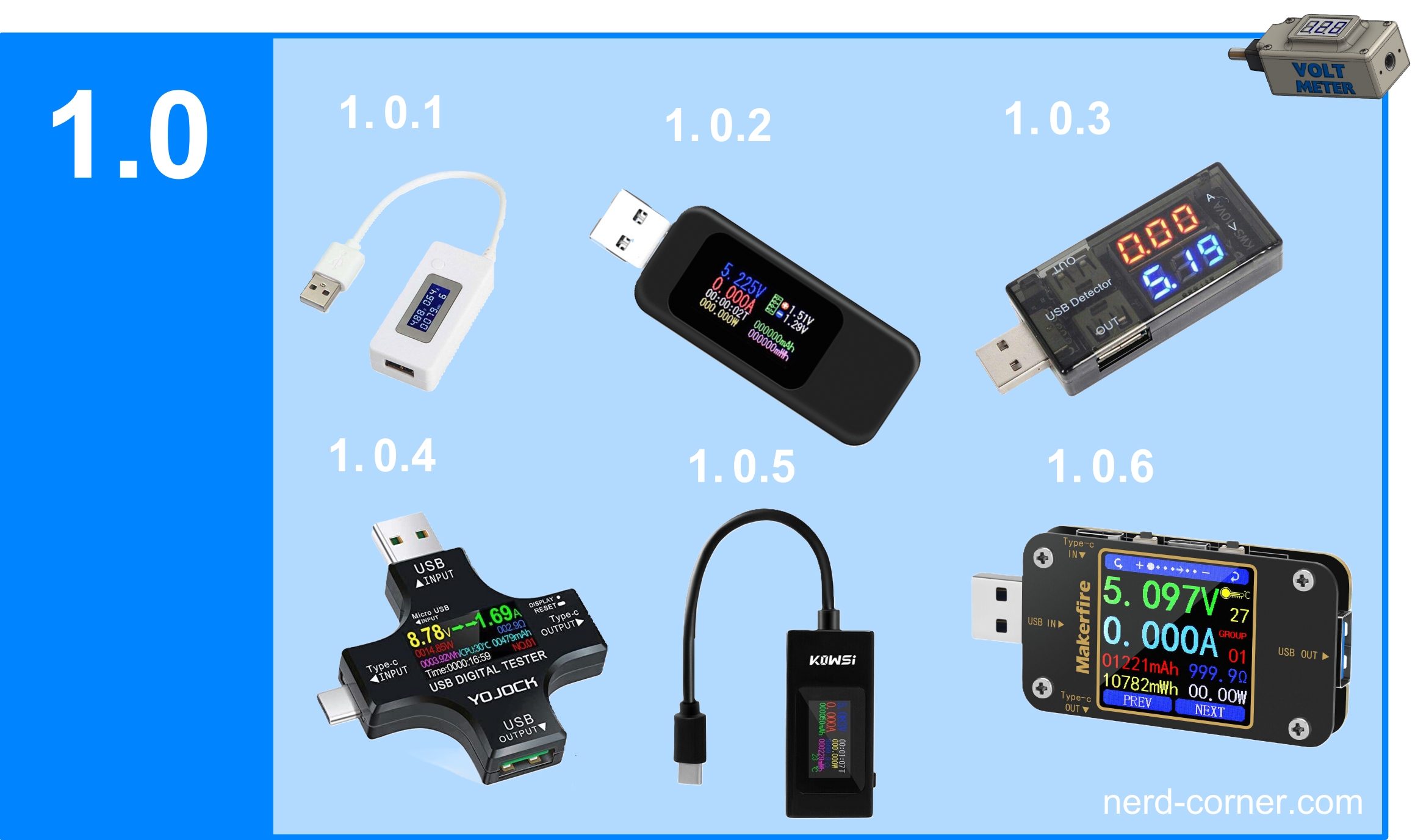
I also use USB multimeters to measure voltage and current, which save the values at the same time. Figure 1.0 shows some USB multimeters that can handle more or less voltage. Some devices are very expensive and the maximum number of amperes that can be measured also varies. If you only want to measure voltage and don’t have much of a budget, my project is just right for you.
This might also interest you: Do it yourself power bank with voltage regulator and voltmeter
List of components
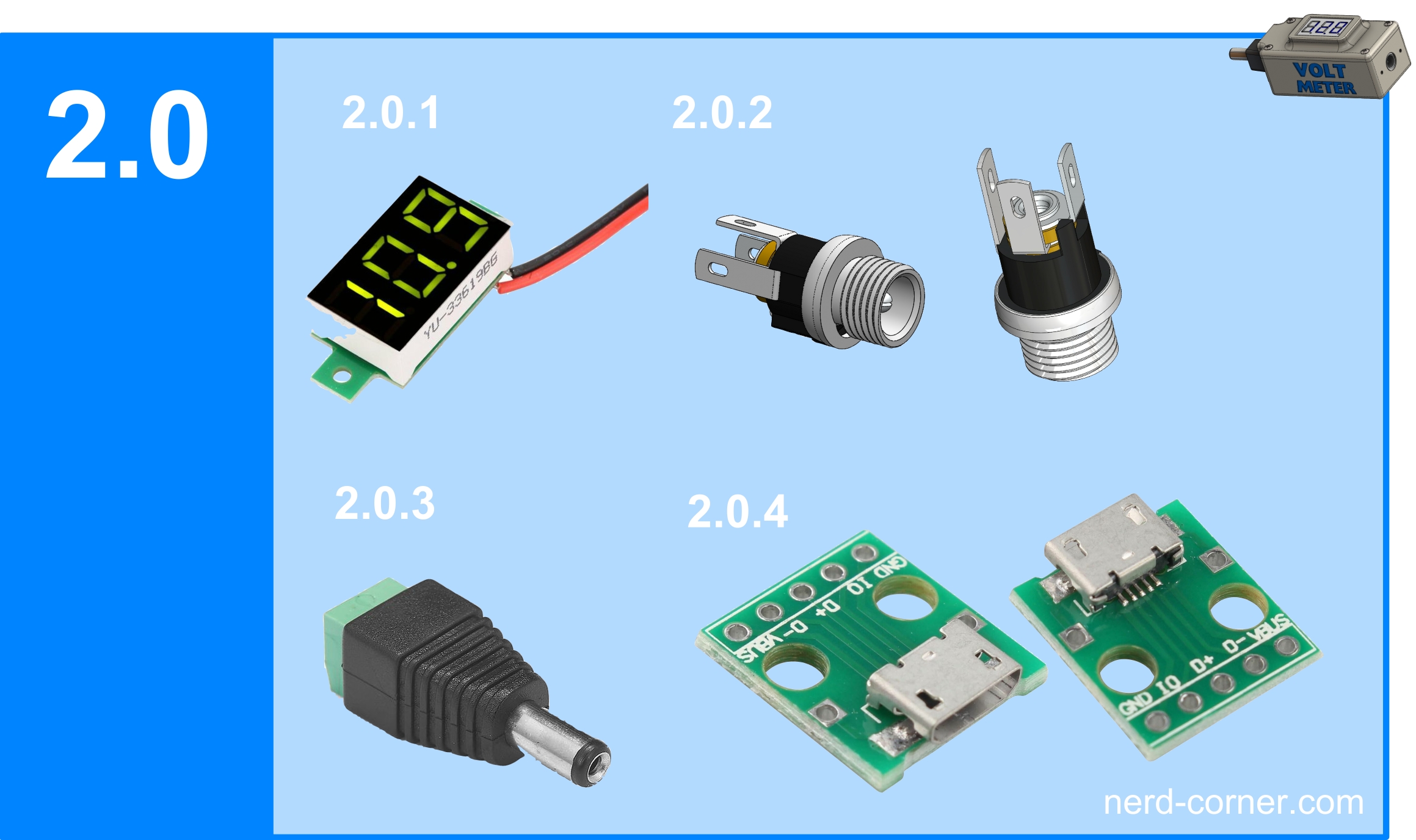
- Mini voltmeter DSN-DUM-368 /or DSN-DMU-368k (Figure 2.0.1)
- Hollow socket 5.5×2.1 (Figure 2.0.2)
- Hollow plug 5.5×2.1 (image 2.0.3)
- USB micro adapter board optional (picture 2.0.4)
- M2 x 10 countersunk head screw 6x (without picture)
- M2 x 4 cylinder head screw 2x optional (without picture)
- Cable 0.5mm² (without picture)
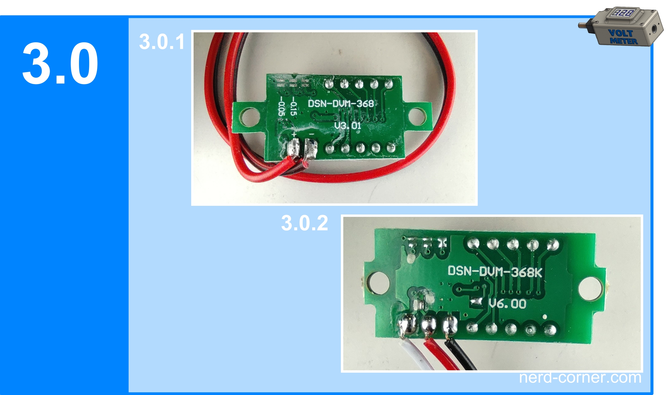
As can be seen in Fig. 3.0, there are two different types of mini voltmeters. The one with two cables (Figure 3.0.1) and the one with three cables (Figure 3.0.2).
The main difference is that with the mini-voltmeter with two cables, the supply voltage is the same as the voltage to be measured (Figure 3.0.1).
However, there is a problem with this variant. If the voltage is below 4.7V, the mini-voltmeter will no longer work as it requires a supply voltage of at least 4.7V. So if you want to measure a voltage below 4.7V, you need a supply voltage above 4.7V and a separate cable to measure the voltage (Fig. 3.0.2).
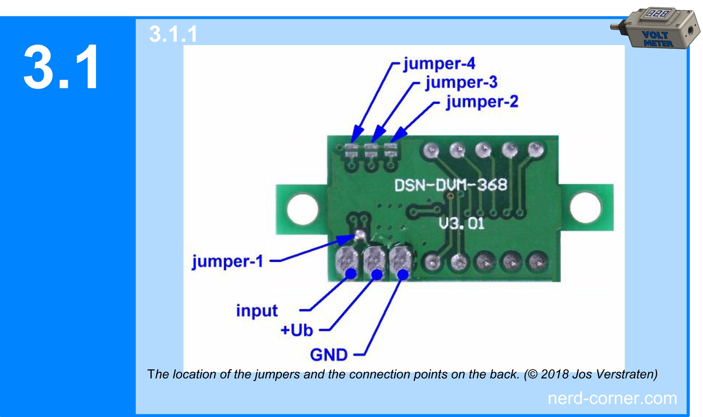
You can also convert a mini-voltmeter with three cables into a mini-voltmeter with two cables. You only need to solder a bridge between +Ub and input at jumper-1 (Figure 3.1.1). Jumpers two to four are used for fine adjustment of the mini-voltmeter (Fig. 3.1.1), in some cases the step widths are printed on as in Fig. 3.0.1.
How such a mini-voltmeter is constructed in detail is documented here or here for example.
Construction
Because of these two different types, I have decided to construct two housings. Let’s start with the variant for the two-cable mini-voltmeter. In the past, I have installed mini-voltmeters in enclosures several times and in doing so have become familiar with the challenges of dimensional accuracy and the diversity of variants from different manufacturers. Despite supposedly standardized components, you often have to reckon with slight deviations in the dimensions. It is therefore important to take larger tolerances into account in the design.
One of the housings I designed was intended for the LM2587 step-up module (Figure 3.2.1). This housing seemed suitable for modification to meet the new requirements. It already contains holders for the hollow plug (2.0.3) and the hollow socket (2.0.2) that I want to use. There is also already a recess in the cover for the mini voltmeter (2.0.1). I am largely satisfied with the dimensions (Figure 3.2.2), apart from the length. What bothers me, however, is the position of the voltmeter in the lid – it should be placed more centrally, i.e. closer to the middle.

First I start with the modification of the lid. I’m happy with the width and height, but the housing is too long. I therefore shorten the cover on the side where the hollow socket (2.0.2) is attached. This does not affect the holder of the hollow plug, as this is already perfectly matched to the plug. When shortening, care must be taken to ensure that the internal components do not touch and that there is sufficient space for the cabling. However, you should not overdo it with the reduction in size, as stability and feel are also important factors in a design.
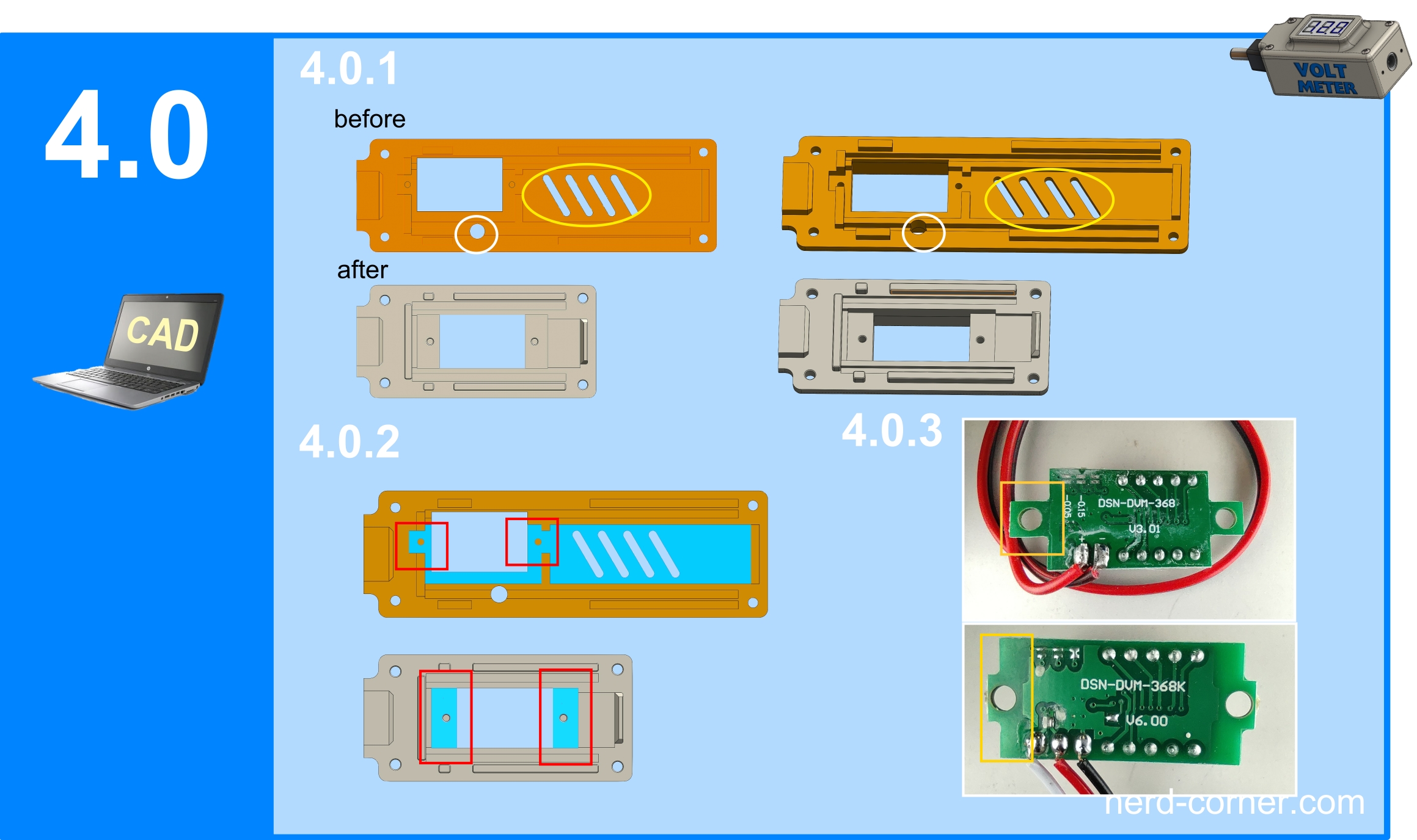
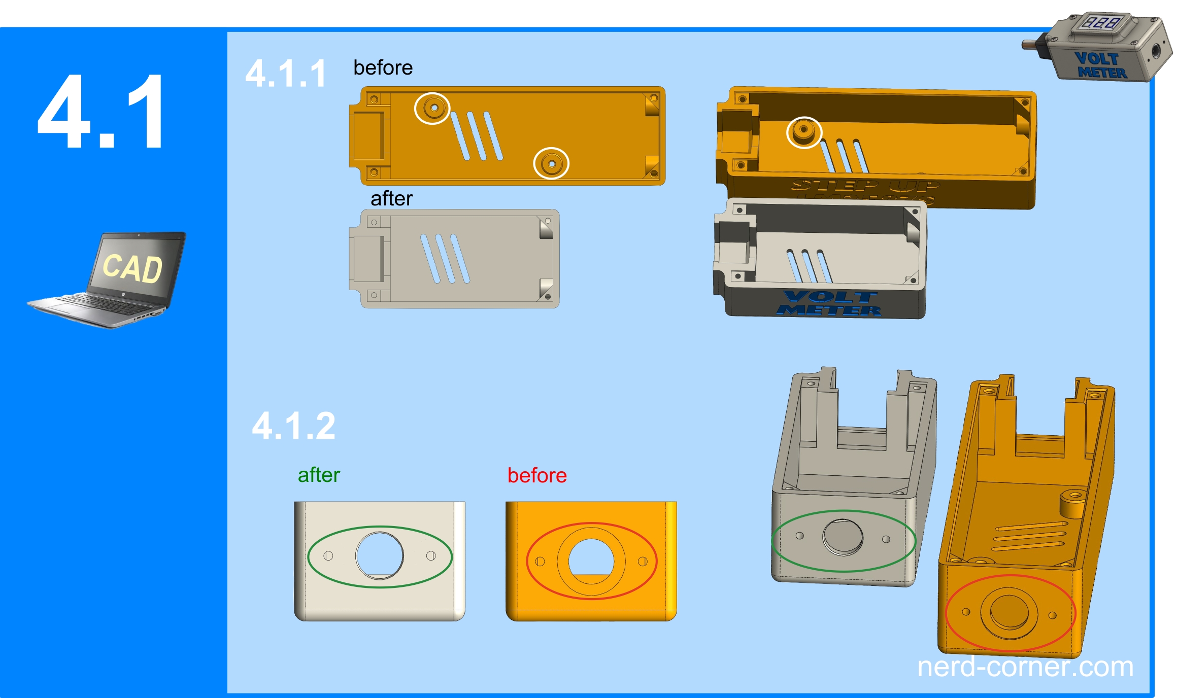
After weighing up all the factors, I shorten the length of the housing or cover to 63.5 mm, and the position of the mini-voltmeter is now centered on the cover (Figure 4.0.1). I have removed the hole for adjusting the LM2587S (marked in white) and the ventilation slots, as no adjustment is required and no ventilation is necessary due to the low heat development.
In picture 4.0.2 (marked in red) you can see that I have changed the recesses or pockets, as some mini voltmeters have a flat surface instead of tabs (picture 4.0.3).
In the next step, I shorten the housing to 63.5 mm, similar to the cover. I also remove the mounting pillars for the LM2587S module, as shown in Figure 4.1.1. On the side of the hollow socket, I remove the recess and move the hole pattern 1 mm upwards, towards the cover (Fig. 4.1.2). Finally, the lettering is corrected to VOLT METER.
3D print of the first variant
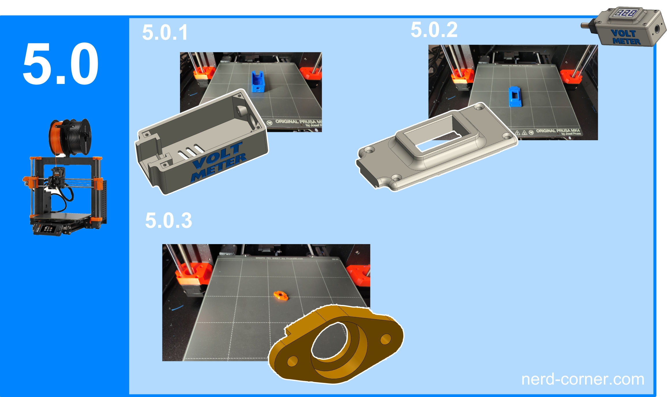
Let’s move on to printing the parts for our variant 1 with two cables. We only need three parts for this variant:
- Housing Fig. 5.0.1
- Cover Fig. 5.0.2
- Hollow socket holder Fig. 5.0.3
There are no special requirements for printing these parts and no special material is needed. In this case, I used inexpensive PLA from a reliable manufacturer. The printing was done on a Prusa MK4 with the usual standard settings.
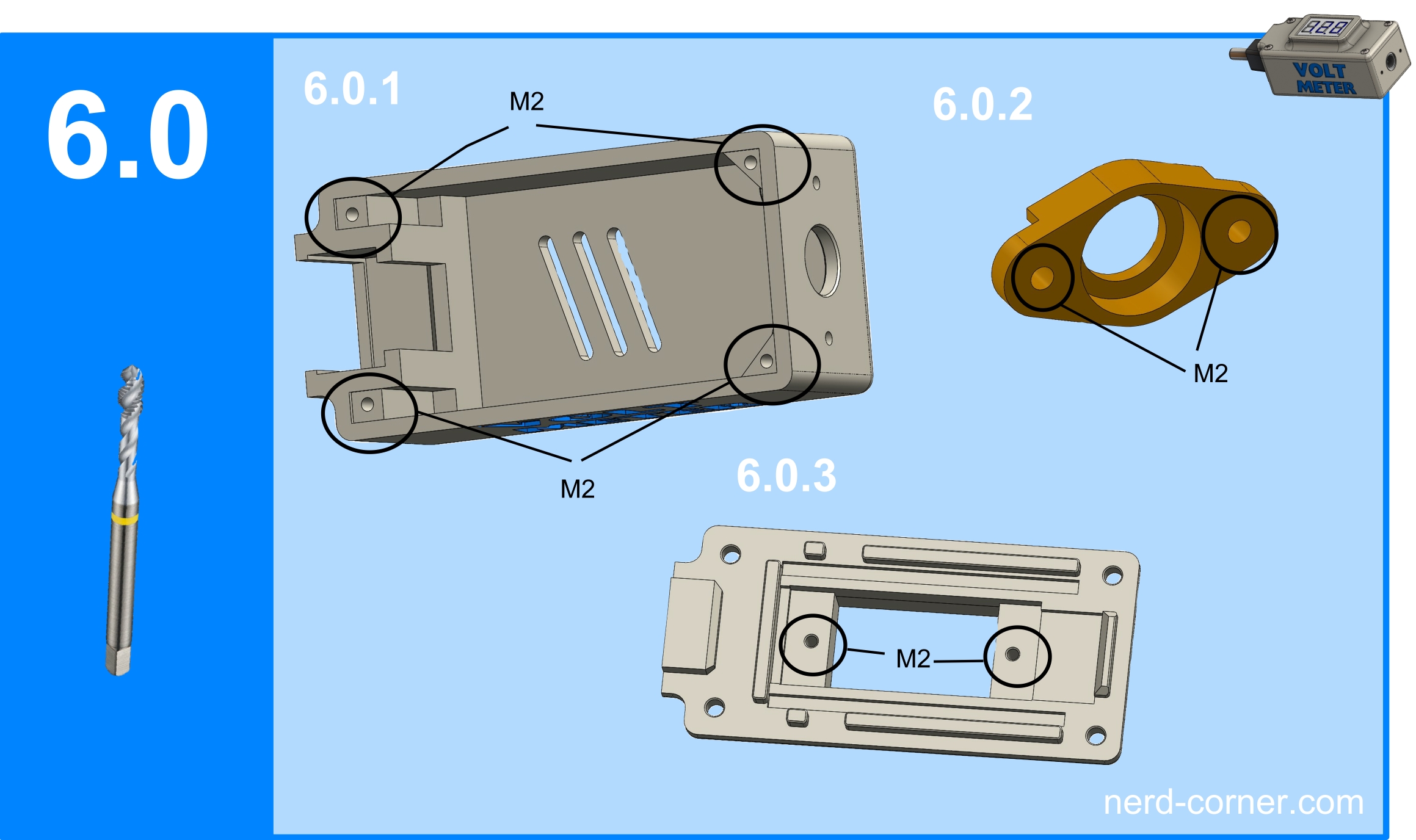
When reworking the printed parts for variant one, only four M2 threads need to be cut into the housing (Fig. 6.0.1) and two M2 threads on the mounting bridge for the hollow bushing (Fig. 6.0.2). Two M2 threads must also be cut in the cover (Figure 6.0.3). Alternatively, self-tapping screws can be used or the parts can be partially glued.
Soldering and wiring the first variant
Once all the parts for variant one have been printed and processed, the hollow socket is soldered to the cables. The positive and negative poles to which the cables are soldered are marked in Figure 6.1.1 (Figure 6.1.2). The cables of the hollow socket and the mini voltmeter are then screwed into the hollow plug (Fig. 6.1.3). Whether the cables are twisted or soldered at the ends is a matter of taste. I always connect the cables of the mini-voltmeter to the current output. Figure 6.1.4 shows the complete inner workings soldered and wired. To stabilize the solder joints on the mini-voltmeter, I reinforced them with a small drop of hot glue. Finally, the hollow socket is inserted into the back of the housing and the hollow plug is pushed into the recess provided (Fig. 6.1.5).

In the penultimate step, I push the mini-voltmeter into the cut-out provided in the cover and secure it by screwing or gluing it in place (Fig. 6.2.1). The cover is then screwed to the housing (Figure 6.2.2). Finally, carry out a function test (Figure 6.2.3).

Construction of the second variant
If you do not want to measure or display the voltage below 4.7 V with the mini-voltmeter, you can stop at this point. However, as I mentioned at the beginning, it is possible to operate these mini-voltmeters with three cables. This option is available if jumper1 (Figure 3.1.1) is not set or not bridged. As the mini-voltmeter requires a minimum supply voltage of 4.7 V in order to function, we need a second voltage source that is above this limit.
In variant one of the housing, however, there is only one input, which is why a second current input is required. As I don’t want to change the dimensions of the housing and there is hardly any space for a second hollow socket, an alternative solution is needed. The solution is a micro-USB board (Figure 2.0.4), which is flat and based on the widely used micro-USB standard.
The question now arises as to where the second connection should be positioned. A side connection would take up too much space, e.g. on a table, as the cable would protrude upwards or downwards at a 90° angle. For me, the best solution is to place the USB port on the same side as the hollow socket.
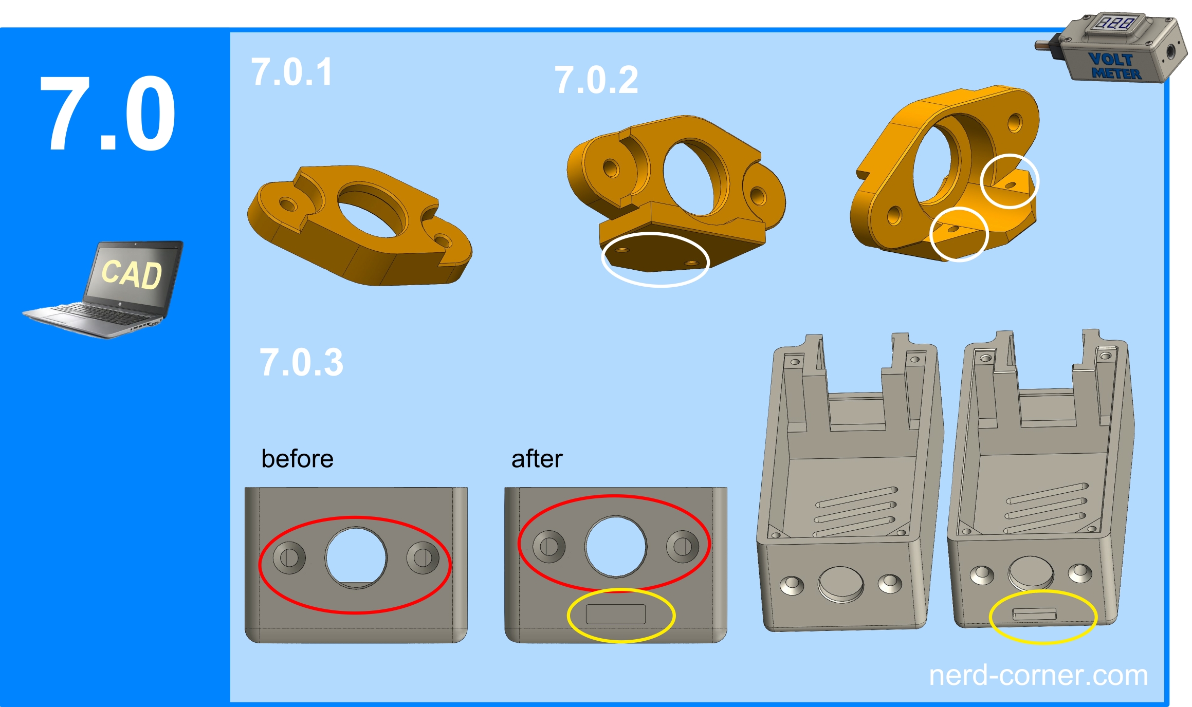
The next question concerns the mounting of the micro USB board: should it be attached directly to the housing or simply glued on? After careful consideration, I decided to mount the board on the retaining bridge of the hollow socket (Figures 5.0.3, 6.0.2 and 7.0.1). In picture 7.0.2 you can see how I attached a plate to the holder bridge. This plate has two M2 threaded holes (marked in white) for attaching the micro USB board and two cut-outs for cables and solder.
On the housing (Figure 7.0.3), the drilling pattern (marked red) must be moved 1.5 mm towards the cover to create space for the slot of the micro USB connector. The slot (marked yellow) is positioned below the hollow socket.
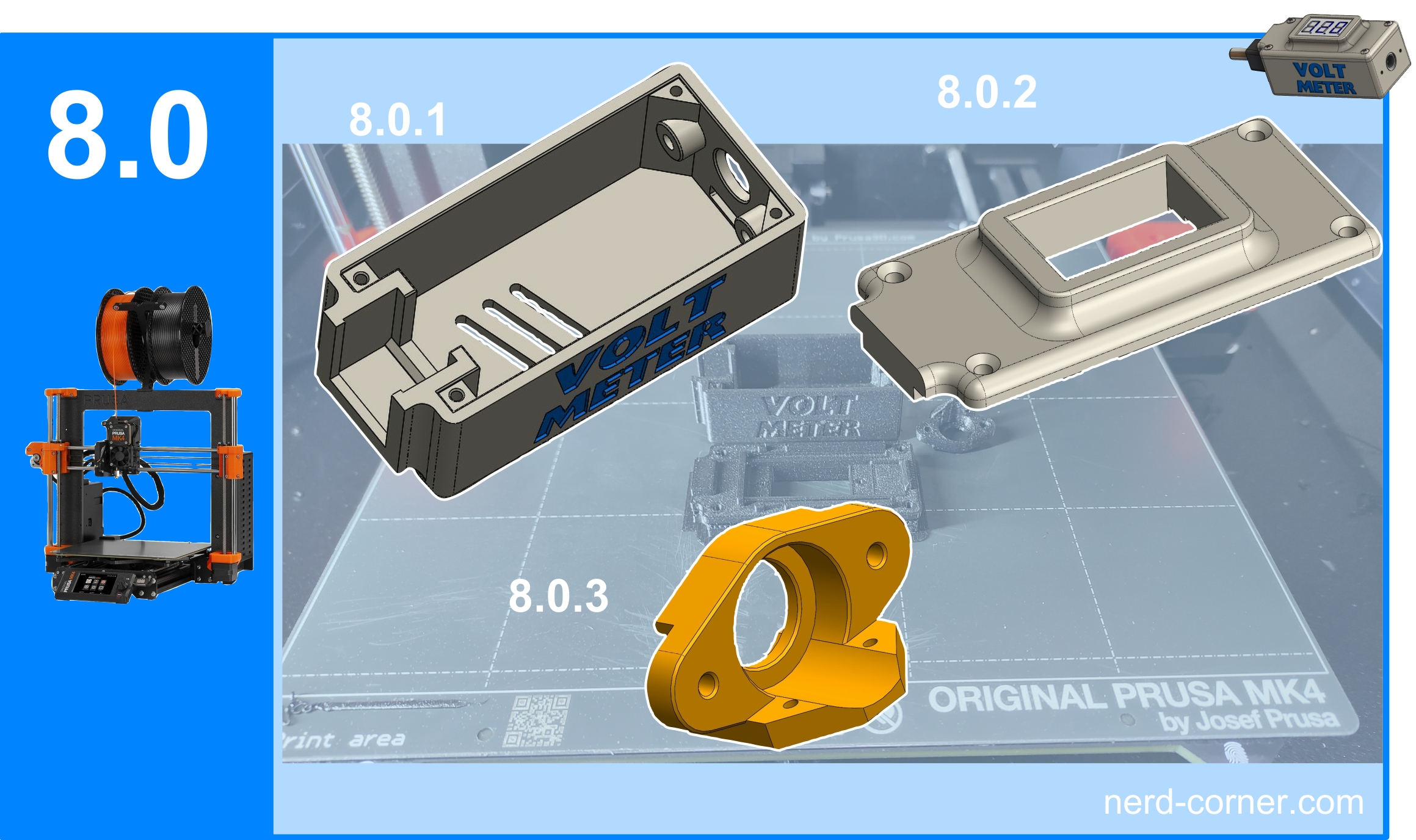
Printing is relatively quick. We need the housing with USB slot (Fig. 8.0.1), the cover (Fig. 8.0.2) and the new holder for the hollow socket and USB board (Fig. 8.0.3).
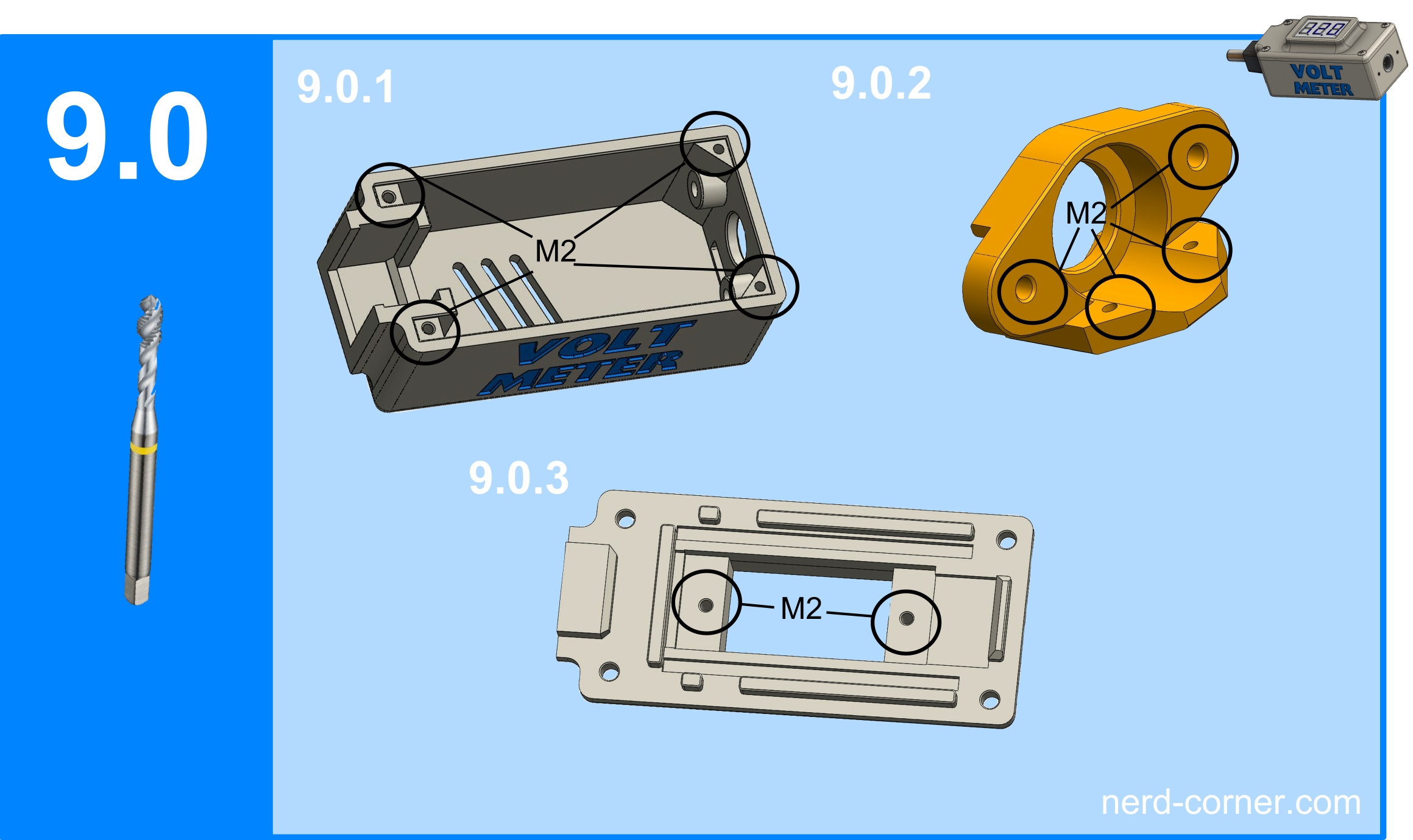
In the post-processing of the printed parts for variant “two”, the thread must now be cut. M2 4x on the housing (Fig. 9.0.1) and 4x M2 mounting bridge for the hollow socket and USB board (Fig. 9.0.2). Two M2 threads must also be cut on the cover (Fig. 9.0.3).
Soldering and screwing the second variant
The parts must now be soldered and screwed together, as in variant one (Fig. 6.1). It should be noted that there is now an additional cable and the wiring is different to variant one. The mini-voltmeter is now powered externally via the micro-USB connection. The negative pole is routed from the hollow socket (9.1.3) to the USB board (9.1.1), then to the mini-voltmeter (9.1.2) and finally to the hollow plug (9.1.4).
The positive cable for the power supply of the mini-voltmeter (9.1.2) goes from the positive pole of the micro USB (9.1.1) directly to the positive pole of the mini-voltmeter (9.1.2). The main power cable runs from the positive pole of the hollow socket (9.1.3) to the positive pole of the hollow plug (9.1.4). The test lead runs directly from the mini-voltmeter (9.1.2) to the positive pole of the hollow plug (9.1.4).

Figure 9.2.1 shows how to screw the USB board (9.1.1) to the hollow socket holder (9.0.2). Figure 9.2.2 shows the hollow socket 9.1.3 and the USB board 9.1.1 completely soldered, screwed to the hollow socket holder and then fixed again with hot glue. The result can be seen in picture 9.2.1.

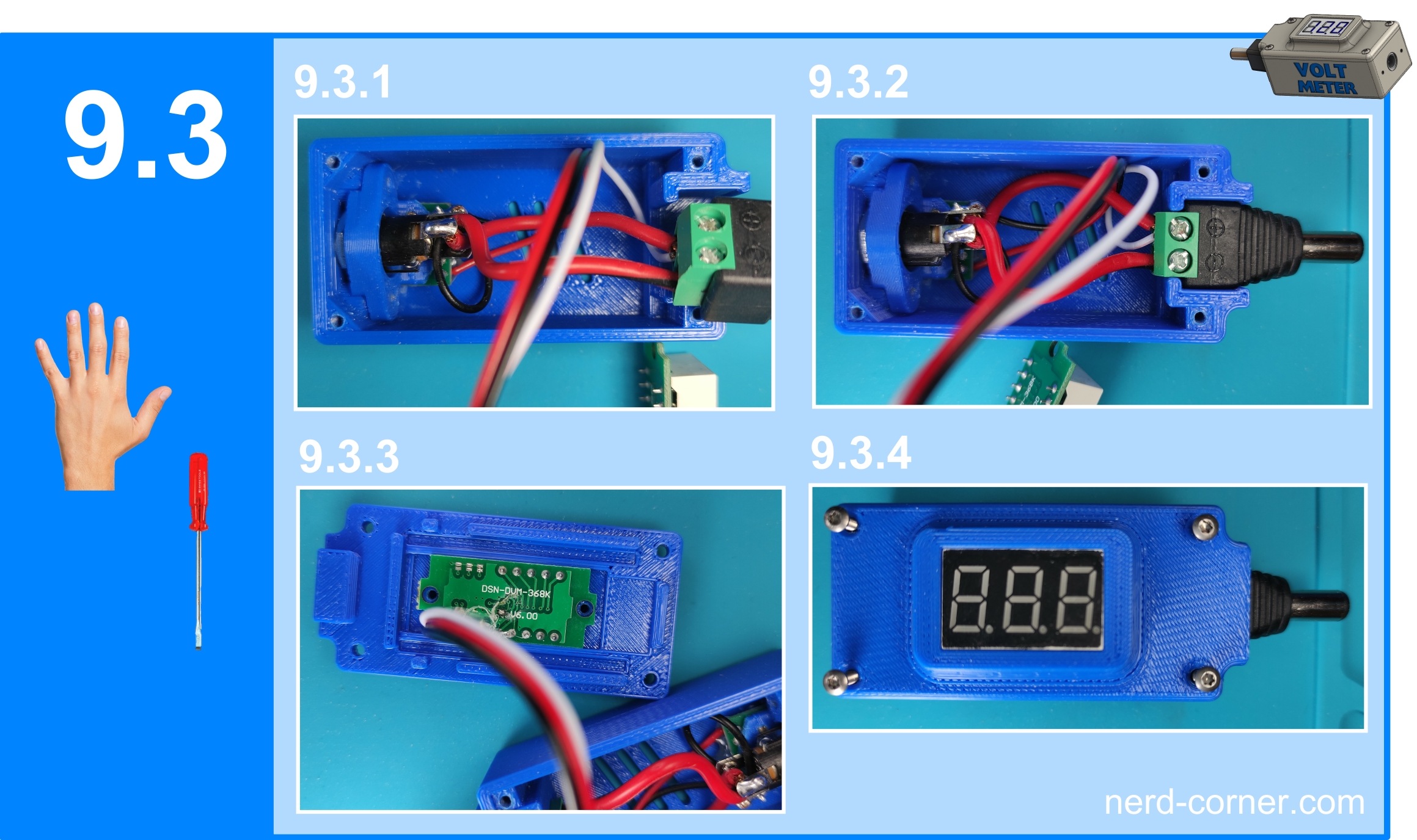
After successfully soldering and gluing, I assemble the mini-voltmeter variant “two”. First, I insert the retaining bridge for the hollow socket and USB board into the back of the housing and screw it in from the outside (Fig. 9.3.1).
The hollow plug is then inserted into the recess provided and pressed down to the bottom (Fig. 9.3.2). Now press the mini-voltmeter into the cover and either screw or glue it in place (Fig. 9.3.3). Finally, the cover is fitted and screwed on with the M2 screws (Fig. 9.3.4).
Function test
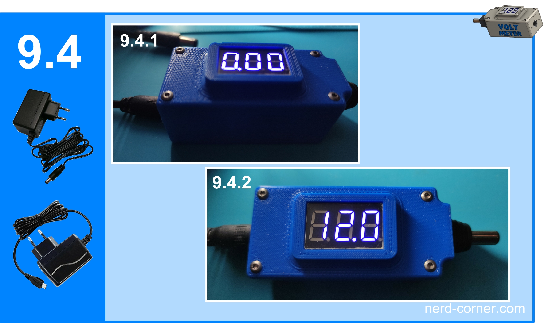
Now it’s time for the essential function test. For this we need a micro USB power supply unit and a 12V power supply unit with a 5.5×2.1 mm hollow plug. First, I connect the micro USB power supply, which supplies 5V, to the housing. The display of the mini-voltmeter lights up and shows zero (Figure 9.4.1). This is the expected result, as there is still no voltage on the line to be measured. Only when I connect the 12V power supply unit with hollow plug does the mini-voltmeter correctly display 12V (Fig. 9.4.2).
Everything works perfectly and adds value for me in the workshop.
