

I found some more possibilities to use the LM2587S voltage converter (step-up DC-DC module) after the development of the first case. The module is extremely useful to quickly supply other devices with voltage. Originally, I just wanted to use it to charge a vacuum cleaner battery and had to set the correct volts once for that.
However, it is impractical to vary the voltages for different devices. First, the input jack is located at the bottom of the case, which unfortunately creates an uncomfortable angle for holding the screwdriver when adjusting the voltage and leaves little room for your fingers. Second, a multimeter is needed each time to measure the voltage. The goal of the adjustments was to improve the handling and the design.
This might also be interesting for you: Development of a charging device from a LM2587S Step-Up
Liste der Bauteile:
- 1x hollow plug 5.5 x 2.1
- 1x screw socket 5.5 x 2.1
- 2x flat head screw M2x6
- 2x flat head screw M2x4
- 4x raised countersunk head screw M2x10
- 1x Module LM2587S DC-DC Step Up
- 2x Pico fuse 3A 125V / 230V
- 1x Mini Voltmeter Digital with LED display 0,36″ (optional)

Housing construction of the LM2587S voltage converter
The vertical position of the socket results from the housing length. Since the power input is now to be on the back, the housing had to be longer. 12 mm was sufficient to install the socket horizontally. Due to the length of the housing, the screwdriver can easily fasten the socket on the inside.
Alternatively, the socket could have been rotated 90°, which would have kept the socket on the side and the length of the housing the same. However, the distance to the opposite wall would be extremely small and problems would arise when screwing. You would need an angled screwdriver or drill mounting holes in the side panel.
Now the bridge bushings had to be modified. Otherwise the bridge would collide with the corner at the ends. The interfering parts on the bridge were removed in CAD. The column height remains the same, since the bottom thickness and the back wall thickness are the same. The lid also had to be adapted to the length and given a cutout or socket for the mini voltmeter.
The voltmeter 3631AS-1
When selecting the mini voltmeter, I chose the “3631AS-1” variant. This voltmeter sits on a circuit board that has tabs with holes so that you can screw it to the housing cover. On this voltmeter the cables are already soldered with the correct colors (red for plus and black for minus). To protect the voltmeter from mechanical damage, I added a frame to the case lid.

The case height does not have to be changed for the LM2587S voltage converter, because there was already enough space in the previous version. The work on the CAD is definitely an advantage here, because the lid can be extended easily without a cutout for the voltmeter and you get a variant “long” for those who do not need a voltmeter, but want to have the input at the back.

As always, the components were produced on the 3D printer and afterwards the thread was cut (in this case M2). Soldering is very simple, like with the predecessor, and the two additional cables from the voltmeter are screwed to the OUT cables on the hollow connector according to the color.
Setting and adjustment of the LM2578S voltage converter
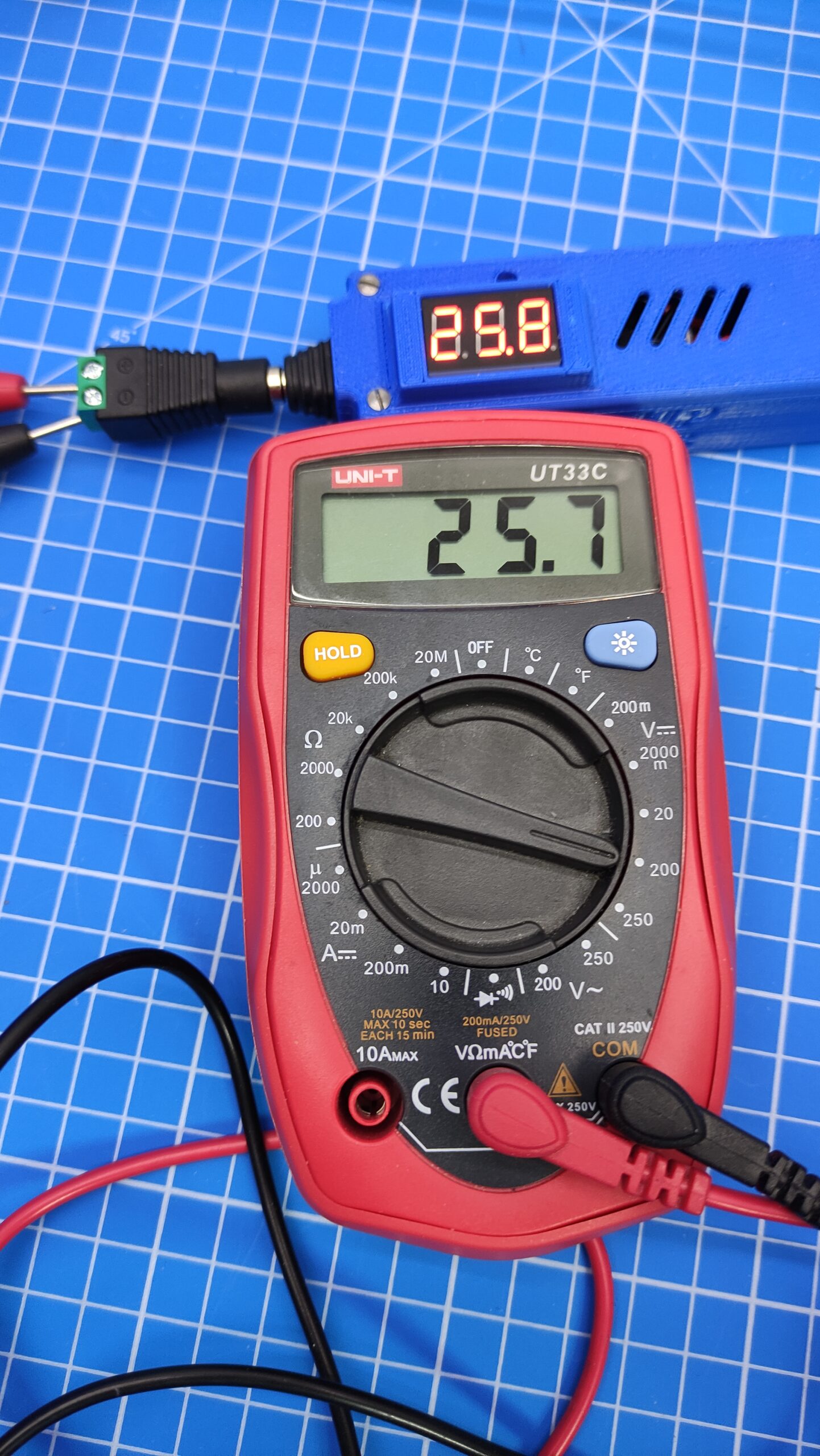
Now to the adjustment of the LM2587S voltage transformer. Here was mainly the accuracy of the voltmeter interesting. Generally the adjustment should be done under load. That means with a connected load (e.g. a resistor). I repeated the measurements several times and was amazed about the accuracy of the mini voltmeter.
The maximum deviation was less than 0.04 V and this even with different input voltages. The device has been extensively tested from 4 V to 32 V. I recommend not using more than 30V output voltage for operation during longer operation, because the voltmeter is not suitable for higher voltages on a long-term basis.
Of course, the contact resistance is important, because each additional connector reduces the voltage. Therefore follows:
- Avoid unnecessary plug connections
- Always measure voltage at the last connection
Safety aspect
The safety should not be forgotten either, since the step-up in contrast to the step-down has an open circuit, it should be provided with a fuse! At my step-up I have subsequently attached (unfortunately not visible in the photos) a lazy pico fuse with 3A at the positive terminal on both the input voltage and the output voltage. Thus, you can start using it!


Download files:
- STL files for 3D printing (with voltmeter)
- STL files for 3D printing (long version without voltmeter)


2 thoughts on “Improved LM2587S voltage converter (Step-Up Modul DC-DC)”