I bought a battery vacuum cleaner, but unfortunately after two weeks I could not find the charging adapter anymore. The specified voltage for the power adapter is 26V. The only power adapter I could find had 24V. However, the 24V was not enough to charge the vacuum cleaner. It just got very warm. But then I got the idea to build a boost converter or LM2587S boost converter with adjustable voltage in my hobby basement.
This might be interesting for you: Arduino control with Bluetooth App

List of components:
- Hollow plug 5.5 x 2.1 1 times
- Screw socket 5.5 x 2.1 1 times
- Flat head screw M2x6 2 times
- pan-head screw M2x10 4 times
- Module LM2587S DC-DC Step Up 1 time

Realization of the LM2587S step-up converter
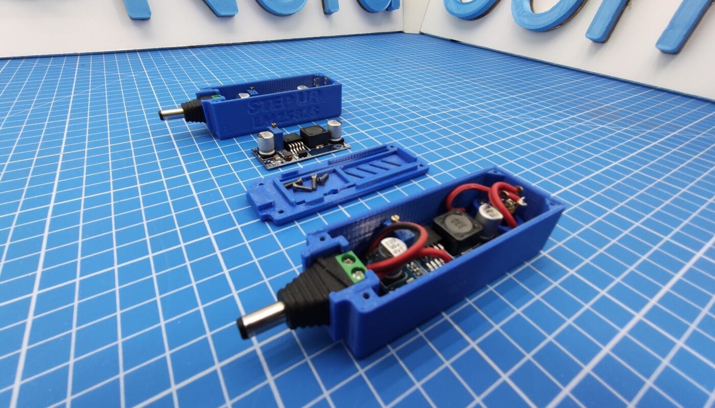
A step-up module is needed. I decided to use a LM2587S DC-DC step-up module, because I already had it at home. Furthermore a plug for the socket at the battery and a socket for the power supply from the antique 24V power supply is needed. Plus some cable, screws and a case to protect the electronics. All parts can be ordered easily, except for the case. This will be designed in CAD. For this, the parts that go into the housing must first be measured, since the official documentation and drawings of the parts are often faulty or not available at all!
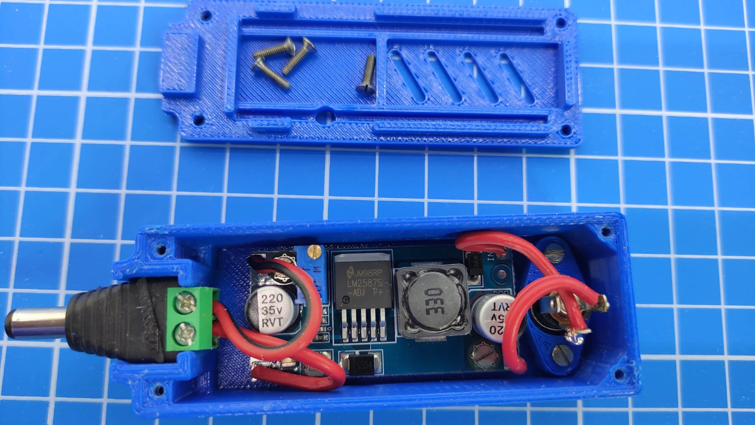
Housing construction
When designing the housing, other questions arise such as:
- Should the housing be plugged directly to the battery or should there be a cable in between?
- Should the connector socket in the case or also be connected to the power supply through a cable?
- Do I need a fan (active) or are ventilation slots (passive) sufficient?
- Should I be able to adjust the voltage without opening the case?
- How big should the case be?
- Etc…
My solution was not to place any cables outside the case and not to use a fan. The size of my case should be about the same as a small powerbank with a 18650 battery. The circuit board should stand on columns inside the case. This has the advantage that the air can flow through better and the length of the thread is longer. By the way, an M2 thread should be sufficient because no large forces occur. The M2 thread is difficult to 3D print, so I cut it with a tap.
On the sides inside the case I left enough space for the cabling. In total only 4 cables are needed. For the socket that takes the plug from the power supply, I use a so-called bridge that stands on columns like the board. In this case the height of the bridge columns is the same as the columns of the PCB. With the bulges on the bridge I regulate constructively how far the socket stands in the housing.
The difficulty is to find the right center position, because the plugs are not all the same length. The lengths of the plugs differ partly up to 2mm! If you put the socket too deep into the housing, the holding mechanism of a short plug can’t grip and the cable including the plug slides out of the socket again. But if the socket is out of the housing, it can be damaged or scratch the surface on which the housing lies. In my experience, the socket should be recessed between 0.5 and 0.75mm in the housing. This is how I implemented it.
For the plug to the battery of my vacuum cleaner I use a standard rubberized screw plug. The challenge was to place this plug with guides in the housing and to press it down with the lid, so that the plug holds and does not wobble! I also planned threaded holes with M2 threads for the screw connection of the lid.
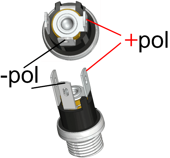
My three components were designed in CAD and then 3D printed. Soldering the electronic components is comparatively easy, because IN/OUT is already printed on the module. Unfortunately, I often confuse plus and minus on the socket, so I have included an illustration. Mostly here is outside minus and inside plus.
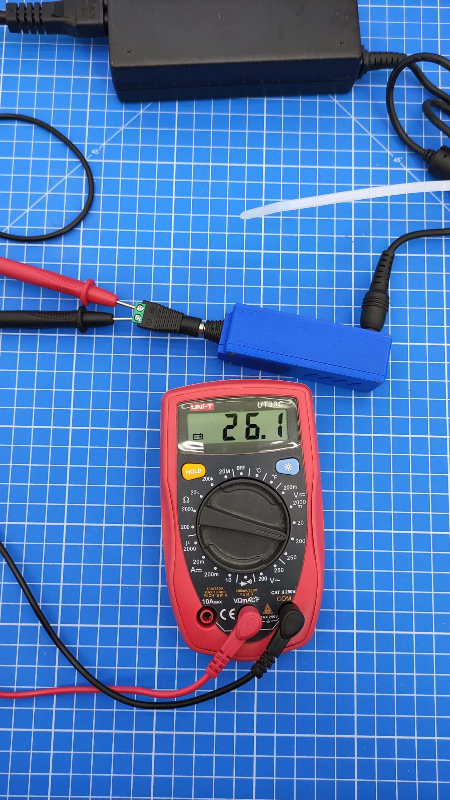
Measuring the voltage of the LM2587S step up
After successful assembly, the LM2587S boost converter is tested and adjusted to achieve the correct voltage (26V) for charging the battery. To measure, simply use a standard multimeter. The best way to adjust the measuring cables is to arrange the cables in a socket with glands. Then plug in the old power supply (23.5V output voltage) and turn the screw on the potentiometer counterclockwise through the hole with a small slotted screwdriver, always keeping an eye on the display. You have to turn the screw a few times to see the result on the display. When the desired voltage is reached, wait at least 15 minutes and readjust again. Mostly the voltage goes up by 0,3V-0,6V after a longer time. If nothing is hot but slightly warm and there is no unpleasant smell of burnt plastic, everything should be fine.
You can use this step-up module LM2587S for:
- Input voltage 3V-30V
- output voltage 4V-35V
- Output current max.5A
LM2587S step-up converter Remark:
- The output voltage should always be 1V higher than the input voltage.
- The input voltage should never be more than 30V
- The input current should be plenty higher than the output current

Download files



2 thoughts on “Step-up Modul DC-DC LM2587S”