
I have recently constructed a housing for a step-up and had good experiences with it. However, since I also need the other direction, which is the downward voltage, I decided to construct a housing for a step-down as well.
This might also be interesting for you: Step-up module DC-DC LM2587S
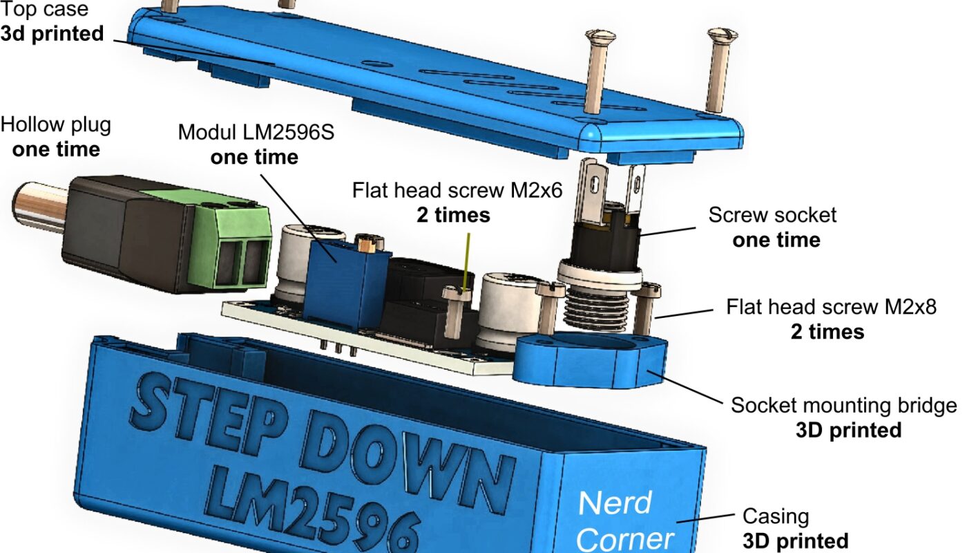
List of components:
- 1 x hollow plug 5.5 x 2.1
- 1 x screw socket 5.5 x 2.1
- 2 x flat head screw M2x6
- 4 x raised countersunk head screw M2x10
- 1 x module LM2596S DC-DC Step Down
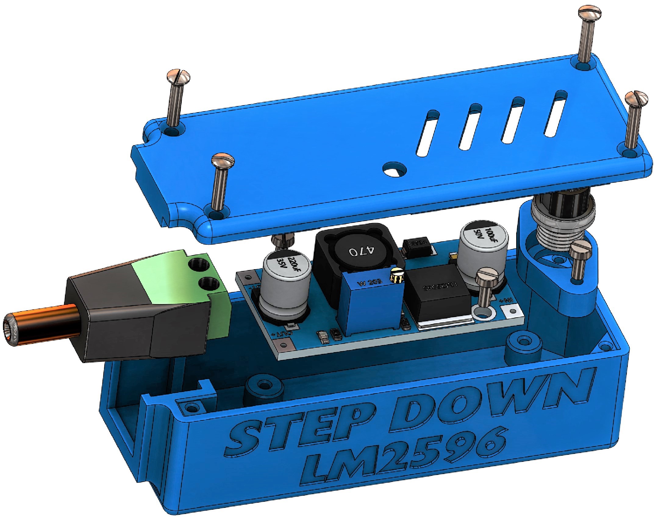
Implementation of the LM2596S step-down
For the step down converter, the DSN2596 was chosen because the module is cheap and widely used. To develop such a switching regulator by ourselves would take a disproportionate amount of time and money. Furthermore, the DSN2596 costs only a fraction of the price of the individual parts that would be needed for a self-developed switching regulator.
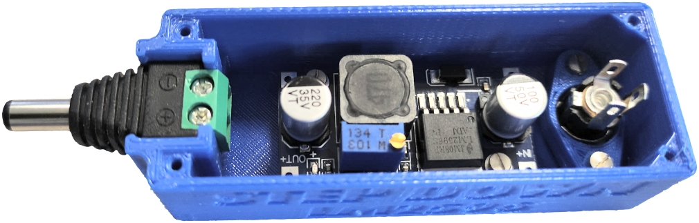
But be careful, some dealers sell DSN2596 modules that do not keep what they promise. It is important that the switching frequency of the LM2596 must not be below 150kHz. If you have an oscilloscope you can measure the ripple voltage at pin-2. The input voltage range is normally between 4 and 35 volts and the output voltage between 1.5 and 30 volts.
The output current is 2A without cooling and 3A with cooling. A heat sink should definitely be used and placed directly on the LM2596! For more than 2A output current, I prefer an XL4015, but this is rarely the case, as the 2A is usually sufficient. As always, the input voltage should be at least 1 Volt higher than the output voltage!
 The efficiency of the module depends mainly on the difference between input voltage and output voltage. This means the higher the difference the more inefficient the module.
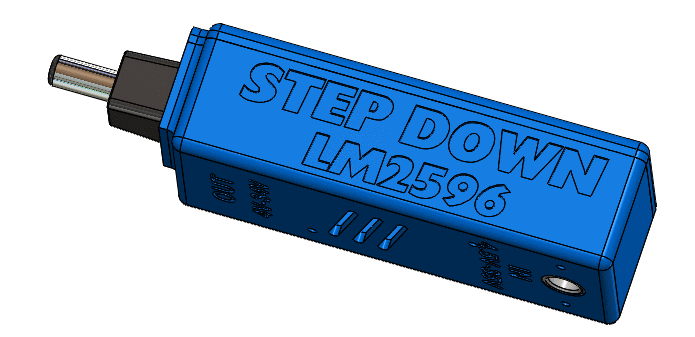
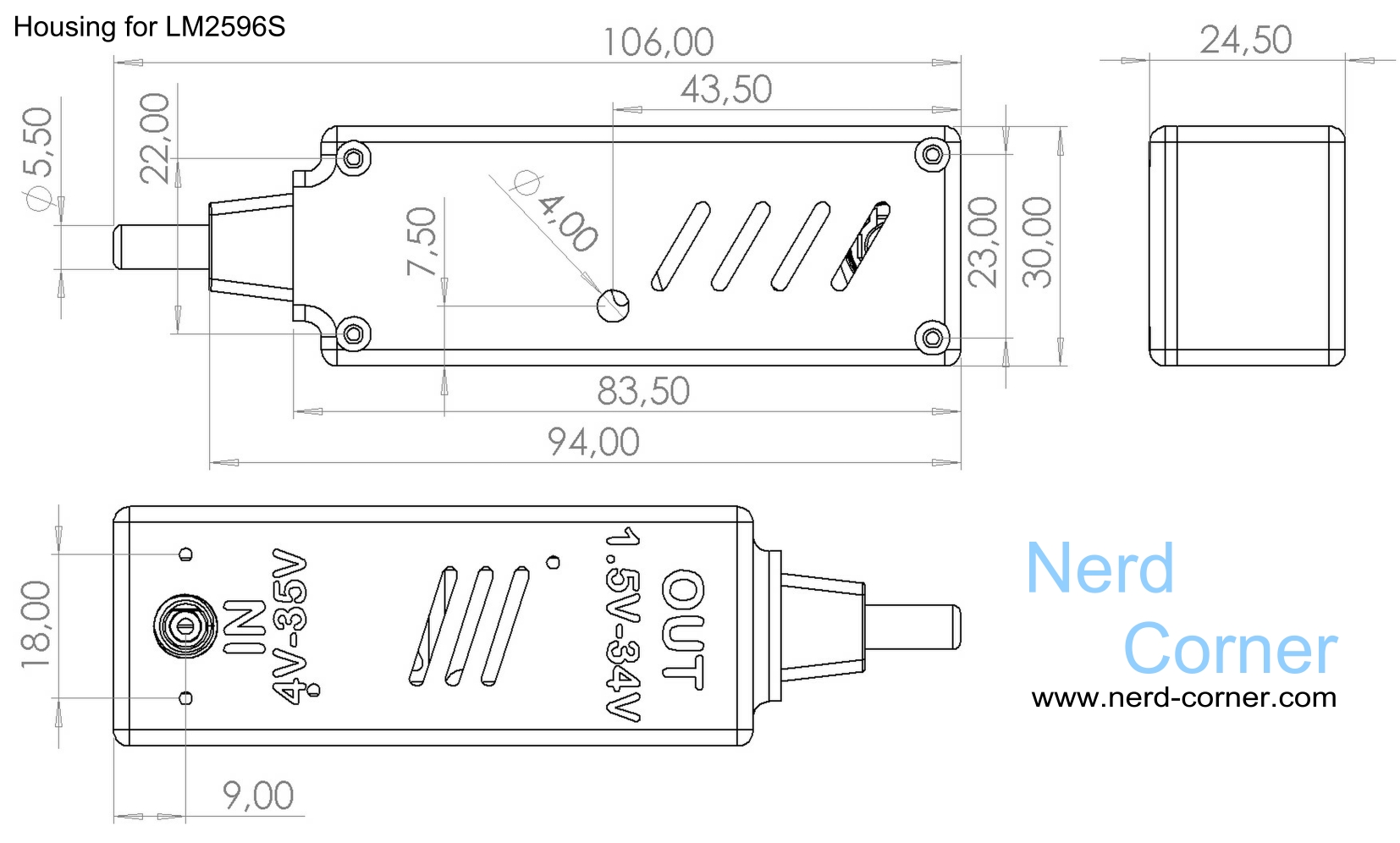
Construction of the case
The housing for the step-down module was developed analog to the housing of the LM2587S. The only differences are the mounting holes for the module and the position of the hole on the lid for adjusting the voltage via potentiometer. If you are interested in how such a case is constructed and what to consider, you can read more about it in the article about the LM2587S.
The following drawing shows how to assemble the case. It is not necessary to use the normal screws for this. The core holes for the M2 thread are also suitable for self-tapping screws. If you have an aversion to tapping or do not have an M2 tap available, you can also use other screws.


One thought on “Step-down Modul DC-DC LM2596S”