In many everyday devices, such as battery-operated radios, lamps, torches and especially laptops, a barrel jack is used for the power supply. In these cases, the barrel jack often serves as a switch: as soon as a plug is inserted, the power supply from the battery, rechargeable battery or other source is interrupted and the device is supplied with power directly from the plug, thus saving the battery. The primary circuit is disconnected purely mechanically.
This might also be interesting for you: Do it yourself powerbank with voltage regulator and voltmeter
List of components
To demonstrate the function, I have decided on a small test setup. I need the following for my test setup:
- Barrel jack 5,5 x 2,1 (1.0.1)
- Voltmeter (1.0.2)
- 5V power supply unit (1.0.3)
- Barrel jack holder (1.0.4)
- Barrel jack Bridge(1.0.5)
- Some cables (1.0.6)

Assembly instructions for bracket and bridge
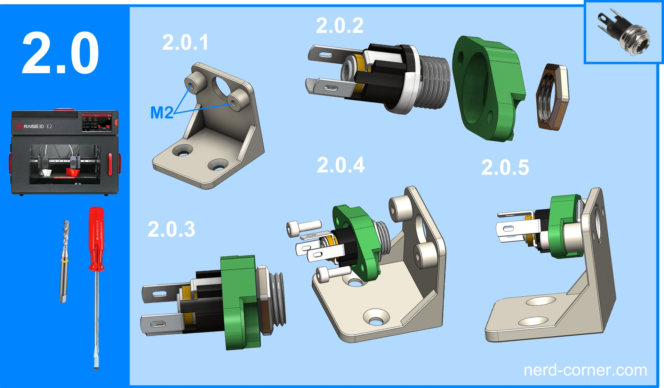
The first step is to print the holder (1.0.4) and the bridge (1.0.5) with the 3D printer. After cleaning the printed parts, I cut two M2 threads into the holder (see 2.0.1). If you prefer to work with self-tapping screws, you can skip this step. The barrel jack is then pushed into the large hole in the bridge (2.0.2) and screwed tight with the nut on the front of the bridge (2.0.3). Fitting the bridge to the bracket is also very simple: Slide the bridge with the recesses on the right and left over the two cylinder surfaces on the bracket (2.0.4) and secure it with M2 screws (2.0.5). The bracket and bridge with the barrel jack fitted form a very stable unit that can absorb large forces. If everything is fitted correctly, the barrel jack should not protrude, but should be recessed by 0.3 to 0.5 mm.

Wiring and soldering the barrel jack
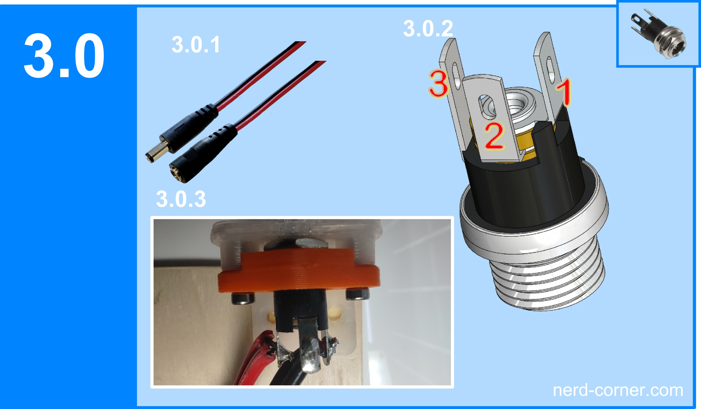
Now we come to the core of this article: wiring and soldering the barrel jack. I use pre-assembled plugs and sockets that already contain crimped cables and a strain relief. The colour coding of the cables is also practical, as red stands for plus and black for minus (3.0.1).
The barrel jack with switching function usually has three solder lugs. The negative pole is always switched, i.e. in figure 3.0.2 this corresponds to number two. The negative pole of the primary power supply, e.g. battery or accumulator, is also soldered on here. Solder lug number one is intended for the common positive terminal; all positive connections are soldered here. The negative pole to the consumers in the device is soldered to soldering lug number three. Figure 3.0.3 shows the complete soldering of the barrel jack.

Assembly and connection
After successful soldering, you can now continue with the rest of the test setup. Firstly, the holder with the soldered barrel jack is screwed onto a wooden plate (4.0.1). The two mini-voltmeters are then attached to the wooden plate (4.0.2). The mini voltmeters are a creation of Nerd Corner. If you are interested in such housings, you can read the corresponding article and download the STL files at the following link.
Now I connect the cables soldered to the barrel jack to the mini-voltmeters (see Figure 4.0.2, pink frame). Next, I connect the primary power source to my 5V power supply and switch it on (see Figure 4.0.3, yellow frame). After switching on the power supply, a voltage is present at both mini voltmeters: 5.35 volts at the supply (red circle) and 5.28 volts at the load (green circle).

Integration of the second power source
As the current flows cleanly via the barrel jack to the consumer, the second power source now comes into play. I operate this with 12 V in order to have a clear difference to the primary power supply. Figure 4.1.1 shows the second power supply with 12.2 volts (turquoise frame).
Now I plug the second power supply with 12 volts into the barrel jack (Figure 4.1.2, blue frame). After a short delay, the value on the consumer’s mini-voltmeter changes to 12 volts (green frame). Nothing has changed on the primary power supply; it remains plugged in and switched on (red frame). The value is still 5.34 volts, which is 0.01 volts lower than before the second power supply was plugged in, but this is due to the fluctuations of the 5V power supply.

As a final step, I remove the 5 volt power supply unit from the primary circuit to check whether there really is no voltage on the primary circuit. Figure 4.2.1 in the yellow frame remains dark and so the test was successful!


