
I bought a socket spanner box (1.0.1-1.0.3) with 50 or 150 pieces and thought I was set for the rest of my life. But unfortunately, something gets lost or broken over time. Most often, the bits are torn out or rounded off at some point and you have to replace them. Replacement tools from the manufacturer are often expensive or no longer in stock. In addition, many tools in the same case set are not compatible with each other. This is due to missing adapters that can form a bridge to other tool holders.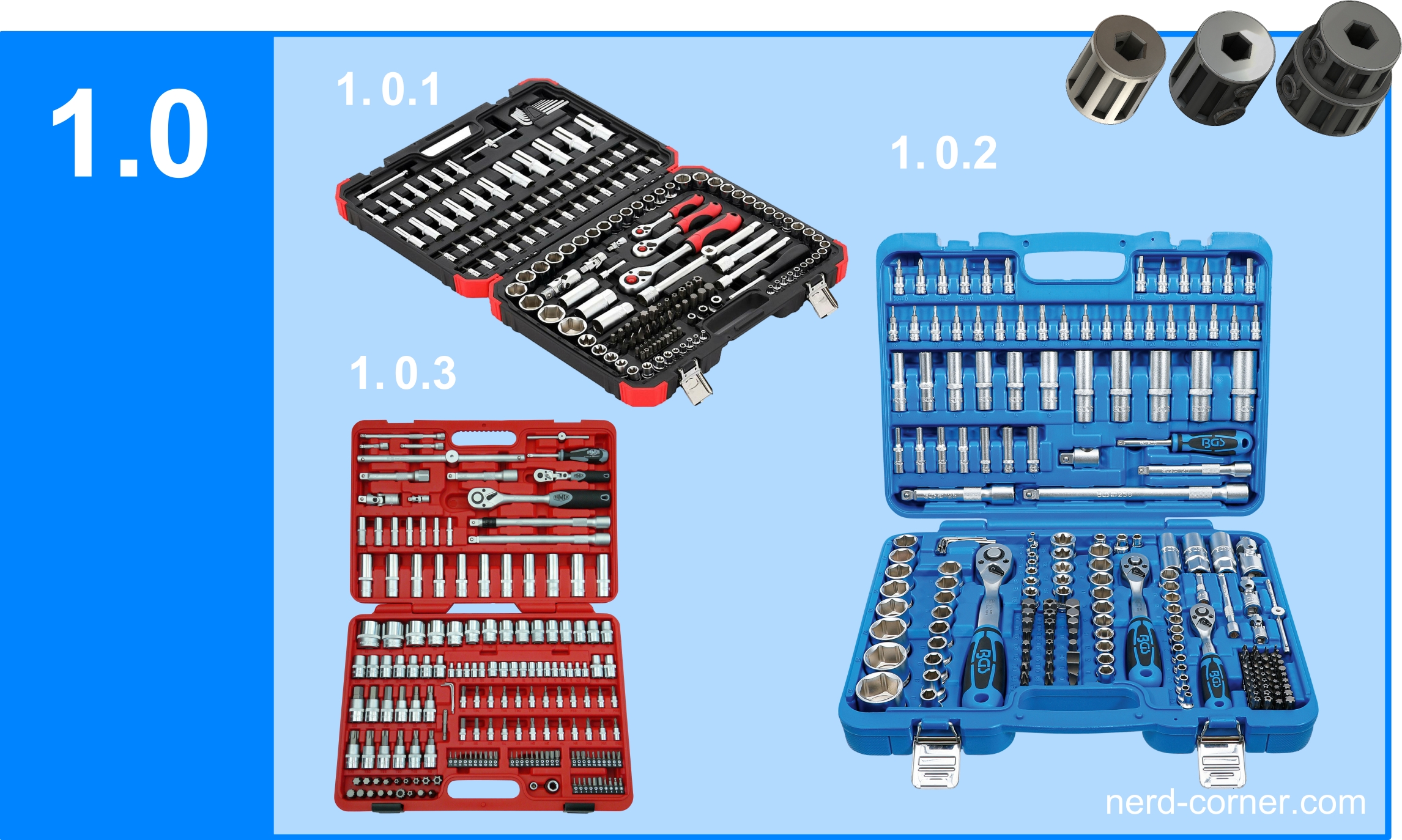
I do a lot of screwing in my workshop and most often I use Torx, hexagon socket and Phillips bits. I always buy these bits in packs of 10 or 25 because they are cheaper and I like to have a small stock. I feel the same way about tools, so I decided to design a few bit adapters and 3D print them.
You might also be interested in: 3D printed battery container
Procedure
The first thing I did was to tidy up my socket cases to find out which adapters are actually needed. The most common square sizes for sockets are:
- ¼” equals 6,35 mm
- 3/8″ equals 9,52 mm
- ½” equals 12,7 mm
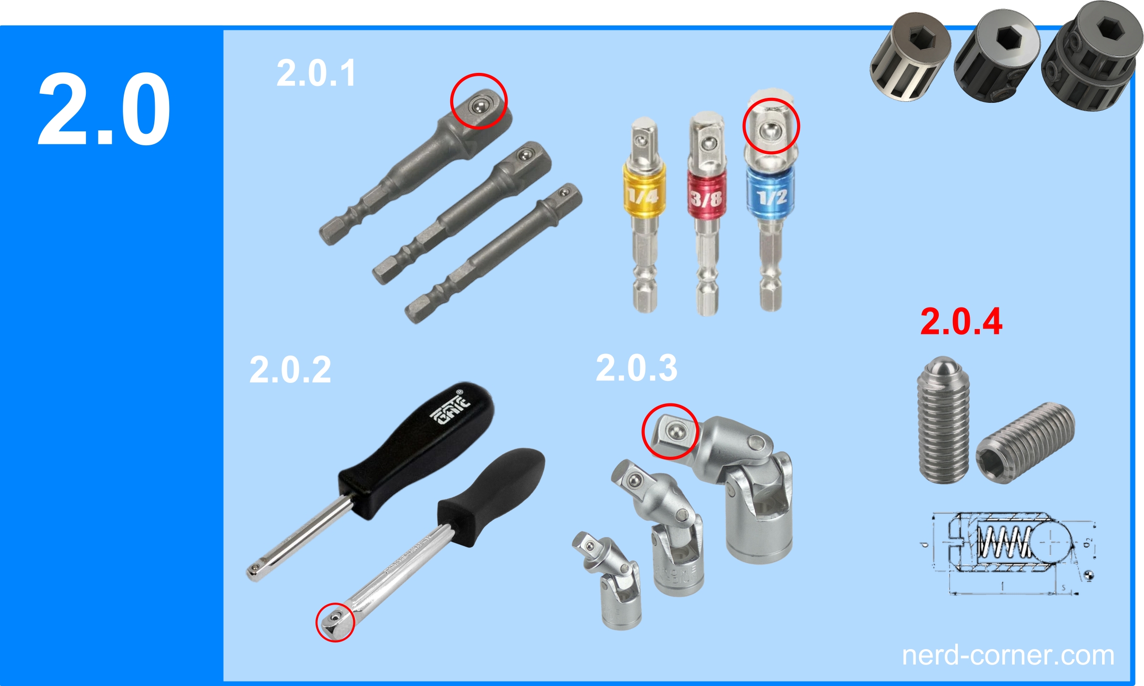
In picture 2.0 I have put together some square photographs. Figure 2.0.1 shows a ¼” hexagonal shaft with three different square sizes. This hexagonal shaft can be easily clamped in a three-jaw chuck which is usually used with a drill or cordless screwdriver. Picture 2.0.2 shows the version with a handle, where the square is at the end of the shaft. In 2.0.3 you can see three joints with different square sizes and picture 2.0.4 shows a so-called “spring pressure piece”. The resilient thrust piece has the task of retracting when inserted into the counterpart and engaging in the intended notch or groove in the counterpart in the final position. This ensures a better hold of both parts in the connection. I have marked the position of the springy pressure piece on the square with red circles on some of the squares as an example. It is important for me to explain the function, because in the construction of the adapter a different solution is realised.
CAD construction of the bit adapter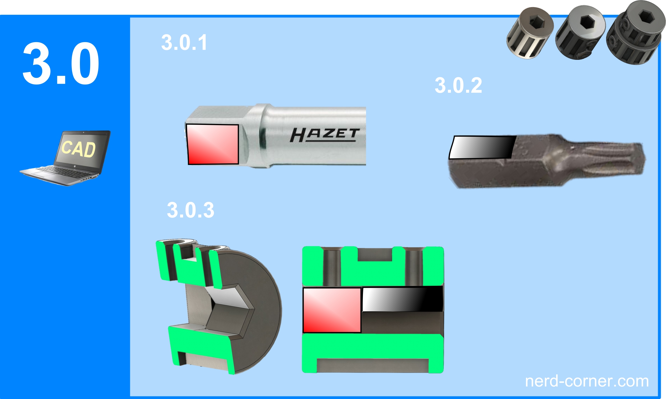
The realisation on the CAD is actually quite quick. The dimensions for the depth of the square on one side and the insertion depth of the hexagon on the other side of the adapter are measured on the shafts. Picture 3.0.1 shows the surface (red) on the square that is pushed into the adapter, which is the same as the surface on the hexagon (black) in picture 3.0.2. In picture 3.0.3 I made a cut and marked the cut surface in green. The placement of the two shafts is shown by the colours.
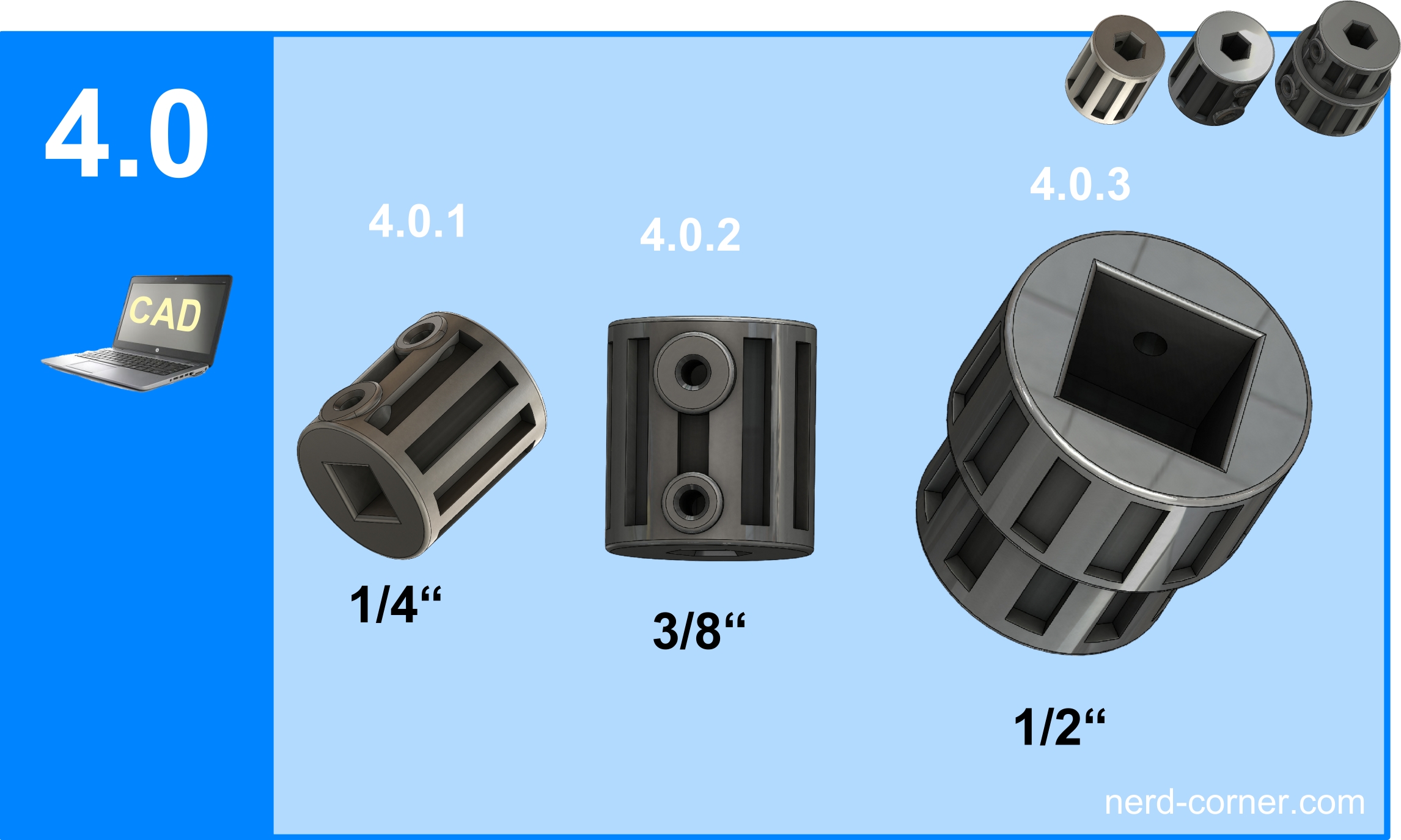
Only the square dimensions are decisive for the outer dimensions of the adapters. Since the square shafts are getting bigger and bigger, the outer diameter of the adapter must of course also be adapted. I have therefore added a step to the ½” adapter (4.0.3). After all, there is enough material in the hexagon as it does not change. The recesses or pockets on the lateral surfaces are not for show. On the one hand they serve the stability of the adapter and on the other hand they save material. The two threads are the same on all adapters. The M3 threads are used for optional clamping of the shafts.
I use studs with a hexagon socket, which are flat at the end in order not to damage the surface of the shafts. You can also use normal screws if they don’t bother you. The position of the threads can be seen in the sectional view in figure 3.0.3.
Excursus on spring-loaded pressure pieces: The spring pressure pieces have already been mentioned in picture 2.0.4. I have been trying to use them in plastic for several years and have always found that they do not work. It is easier to design the clamping with screws and it is guaranteed to work!
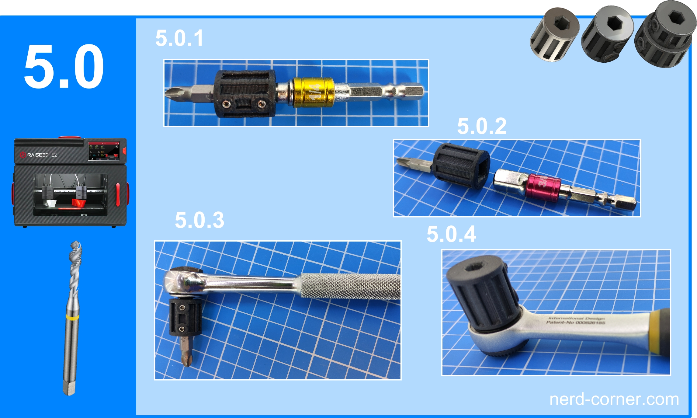
Finally, the bit adapters are printed and cleaned and the M3 threads are cut. In the pictures under 5.0 you can see some examples for the use of the adapters.
Note
The bit adapters are of course only suitable for use under 15Nm. I easily reached this value with carbon fibre reinforced filament. With higher values there is a risk of breakage and therefore also a risk of injury!