
Who has ever had trouble with the adhesive on an LED strip? Nobody? Well, in my opinion, you have. Here comes the remedy! I call it the SMD5050 LED strip bracket.
This might also be interesting for you: Magnetic clamp for strong neodym magnets
Production of the LED strips
You also need to know how such LED STRIPS are manufactured, the misconception that the strips are fitted on an endless belt and cut as required is wrong. The strips are stretched 500mm long in a placement machine and fitted with the LEDs. The number of LEDs depends on how many LEDs are needed per metre. There are strips with 30/60/144 LEDs per metre. The 500mm strips are then soldered together at the ends to the required length.
Realisation of the SMD5050 bracket
As always, I first look for all available LED strips from my collection that contain an SMD5050. It was important to have all the variants from the different manufacturers. This way you can find the best possible middle way to apply the function (i.e. the clamping) to as many variants as possible.
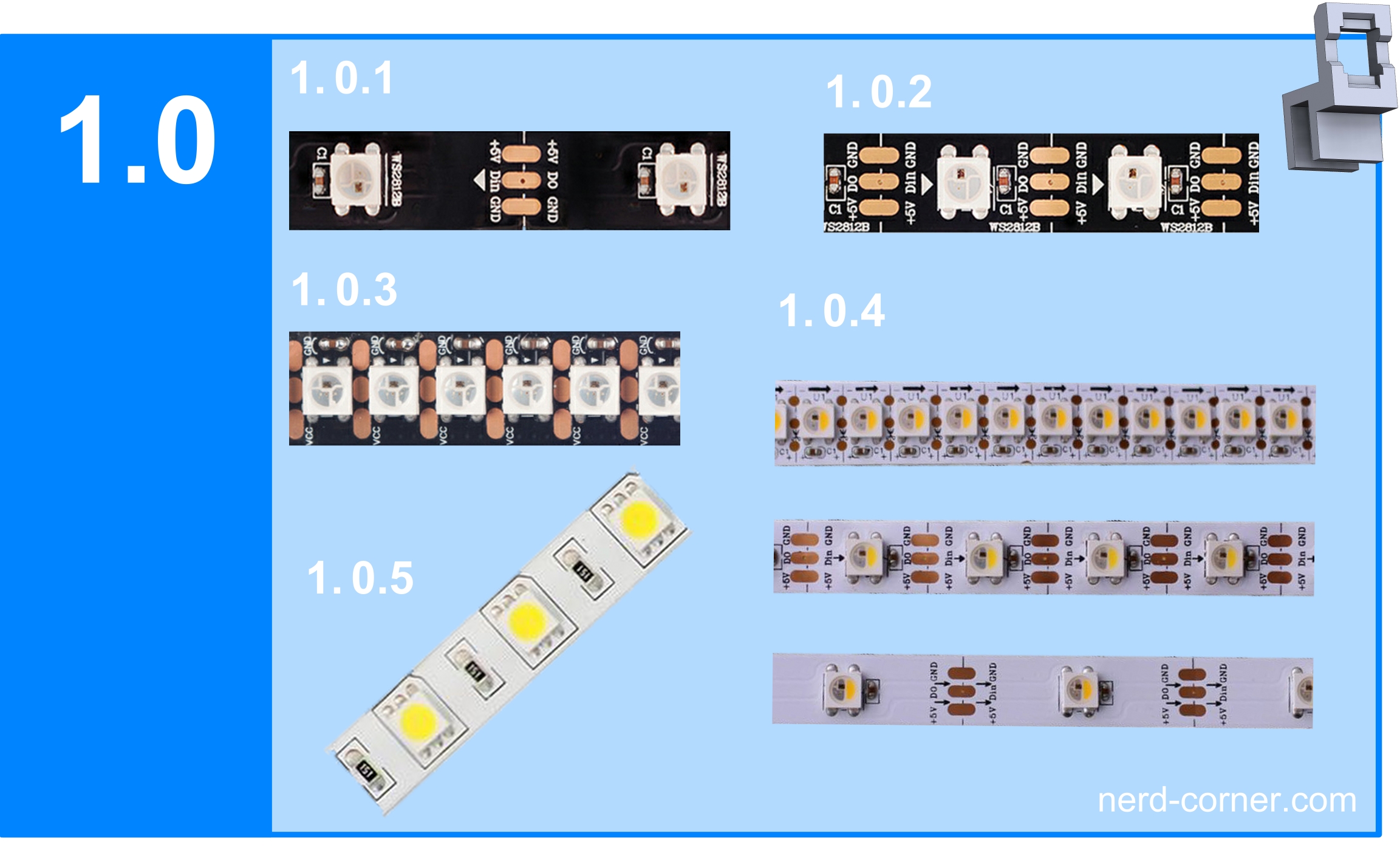
The idea was not to glue the strip to the back, but to clamp the LEDs to the outer surfaces. Figure 1.0 shows some of the numerous variants for SMD5050
- 1.0.1 WS2812B strip with 30 LEDs per metre
- 1.0.2 WS2812B strip with 60 LEDs per metre
- 1.0.3 WS2812B strip with 144 LEDs per metre
- 1.0.4 Sk6812 strips with the same subdivisions as above
- 1.0.5 Cold white strip with 60 LEDs per metre
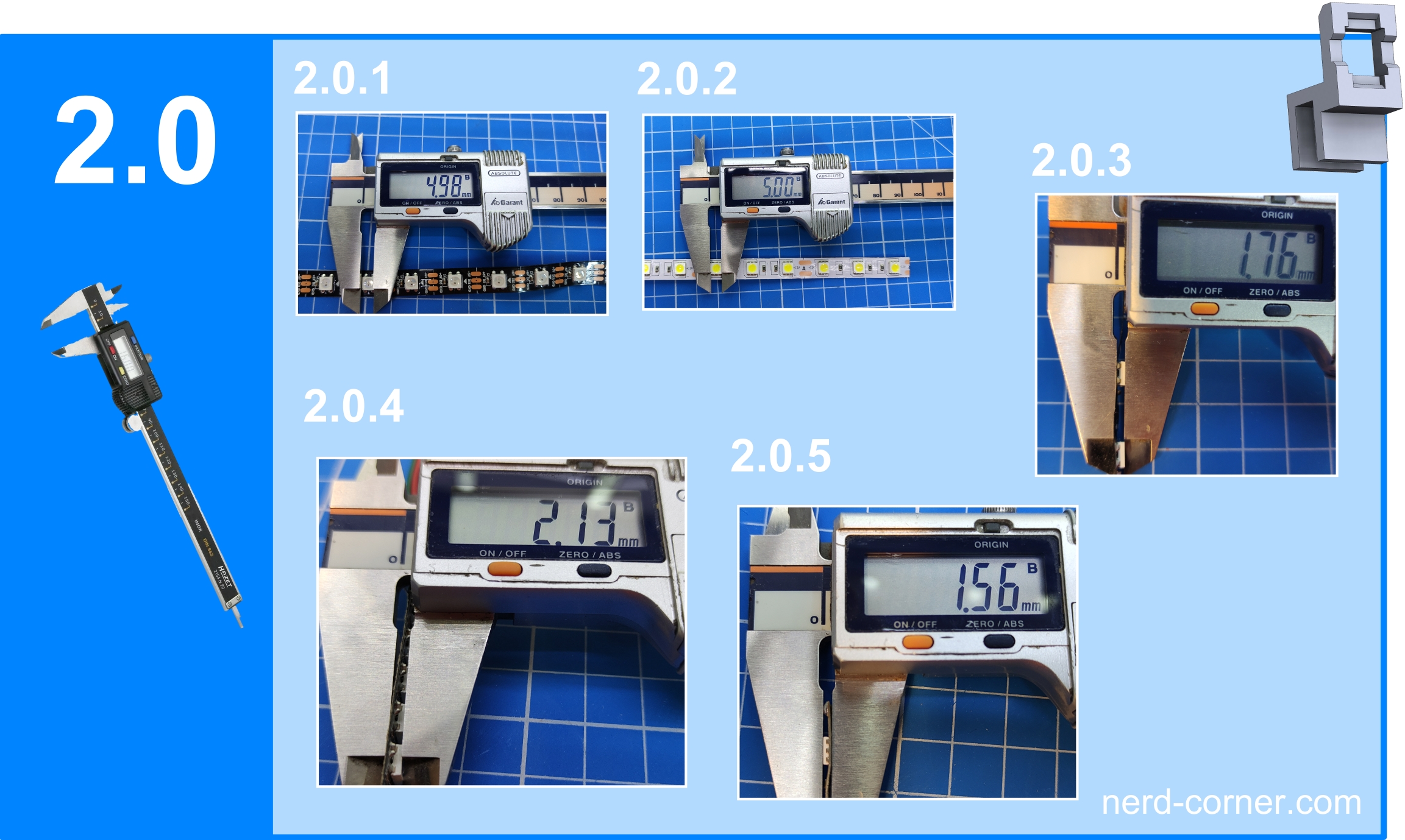
The next step is to measure and compare the outer dimensions of the SMD5050. As the name SMD5050 implies, the numbers 5050 stand for the mass of 5mm on the outer lines (5050 is equal to 5mm long and 5mm wide). To my astonishment, the SMDs are only a hundredth of a millimetre apart. This means that the deviations are marginal (2.0.1, 2.0.2) and negligible for the design.
The situation is different with the height of the LEDs, where the differences are somewhat more striking (2.0.3, 2.0.4 and 2.0.5). But the biggest difference lies in the soldering with more or less solder. The differences are now known and can be taken into account in the design.
The solder joints and external resistors cause the most problems. The solder joints are often very different, sometimes slightly thicker and sometimes protruding beyond the side edge. The resistors are also positioned in different places depending on the strip.
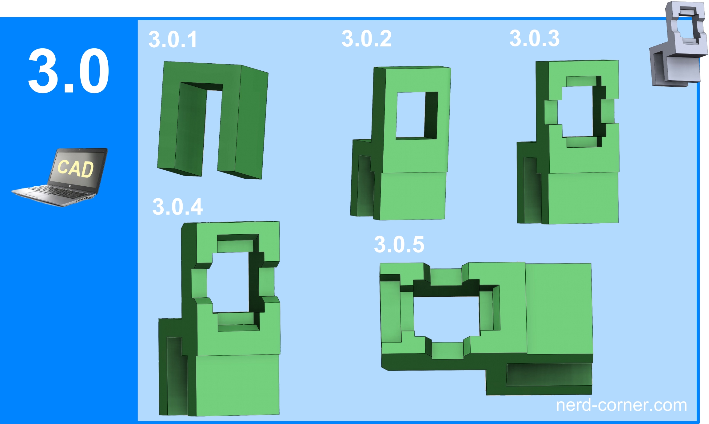
First I draw the retaining clip (3.0.1) to which the LED will later be attached. Next, I design the holding frame for the SMD5050, which will later be used to clamp the LED (3.0.2). In picture 3.0.3 I add so-called recesses. I measured these recesses in the frame for the various LED strips.
After these three main steps, I print the first prototype with my favourite material and favourite printer. After the first attempts to clamp the LED, I was very confident that it would work in the end. Of course, you have to keep an eye on the stability of the clamp when removing the material.
The development is based on my previous experience. It’s a balancing act between holding force, stability and printability. The number of printed prototypes, in this case fifteen, says only a little about the work that has been done. Fifteen attempts is rather few. I was lucky with the basic concept and that the idea was the right one.
In pictures 3.0.4 and 3.0.5 you can see the changes to 3.0.3 in the dimensions and shapes, such as the addition of bevelled edges.
Manufacturing the clamp in the 3D printer
The CAD development is now complete. The next step is the printing process. A number of factors need to be taken into account, such as the correct calibration of the 3D printer. If you print a housing with a lid on a poorly calibrated or uncalibrated 3D printer with the same settings and material, it will always fit together. The dimensions are not correct but the covers of the housing and lid are the same and therefore it still fits.
The situation is different when an externally produced component such as the SMD5050 comes into play. Then the dimensions must match within a certain tolerance range. If you don’t want to calibrate your 3D printer, you can adjust the dimensions using the slicer. Every slicer offers a so-called scaling function. The next factor is related to the size of the clamp, as the clamp is very small, the nozzle cooling must be set to 100%. Nozzle cooling is actually the wrong term, as it is not the nozzle that should be cooled, but the filament that emerges. With small components, the hot nozzle passes the workpiece again more quickly so that it cannot cool down properly. As a result, the filament runs and cannot hold the desired shape.
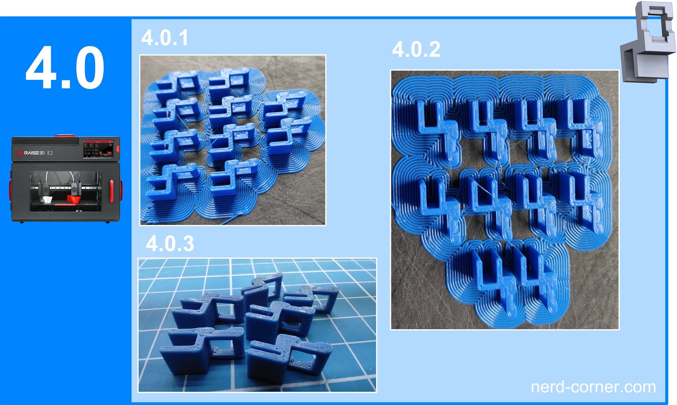
The printing direction should also not be underestimated. With our clamps, the printing direction should be sideways, i.e. printed horizontally (4.0.1).
Mounting the SMD5050 LED strip bracket
To mount the clip, it is advisable to place the individual LED or strip on a flat surface and then press the clip on from above. The LEDs are very stable and can withstand a lot. If you have any doubts about the holding power of the connection, you can of course add some glue. It is also not necessary to clamp every LED to the strip, it is sufficient to clamp every third or fourth LED.
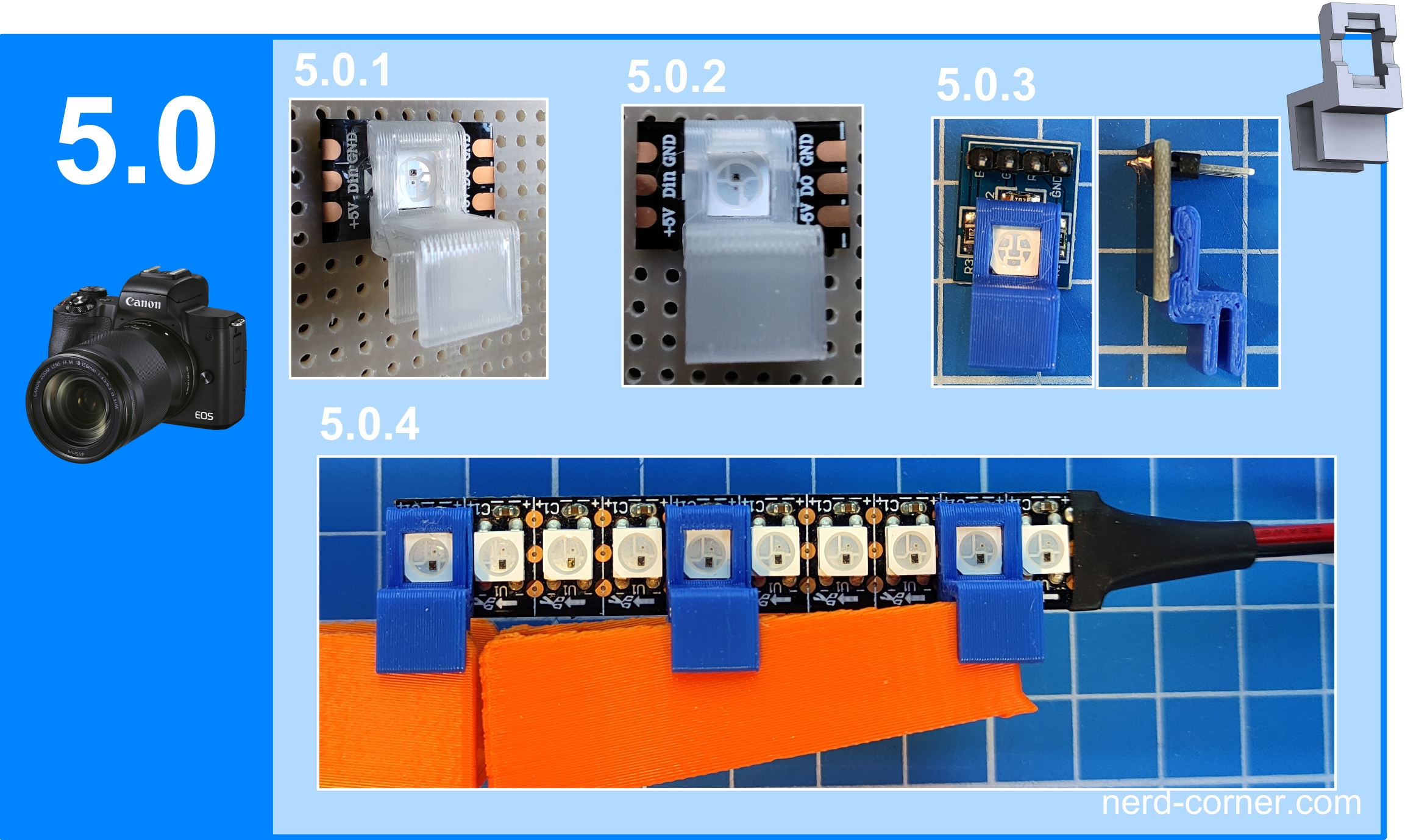
I have designed different types of clamps that can be screwed, clamped and, of course, glued. However, there is one restriction. The clamp can only be attached in two directions. I had to make the compromise in the design that only two sides are suitable for clipping. This means you can’t turn and attach the clip every 90 degrees, but only 180 degrees. In short, the soldering points must always be to the right and left of the clip and not at the top and bottom. (see pictures 5.0 – 5.1)
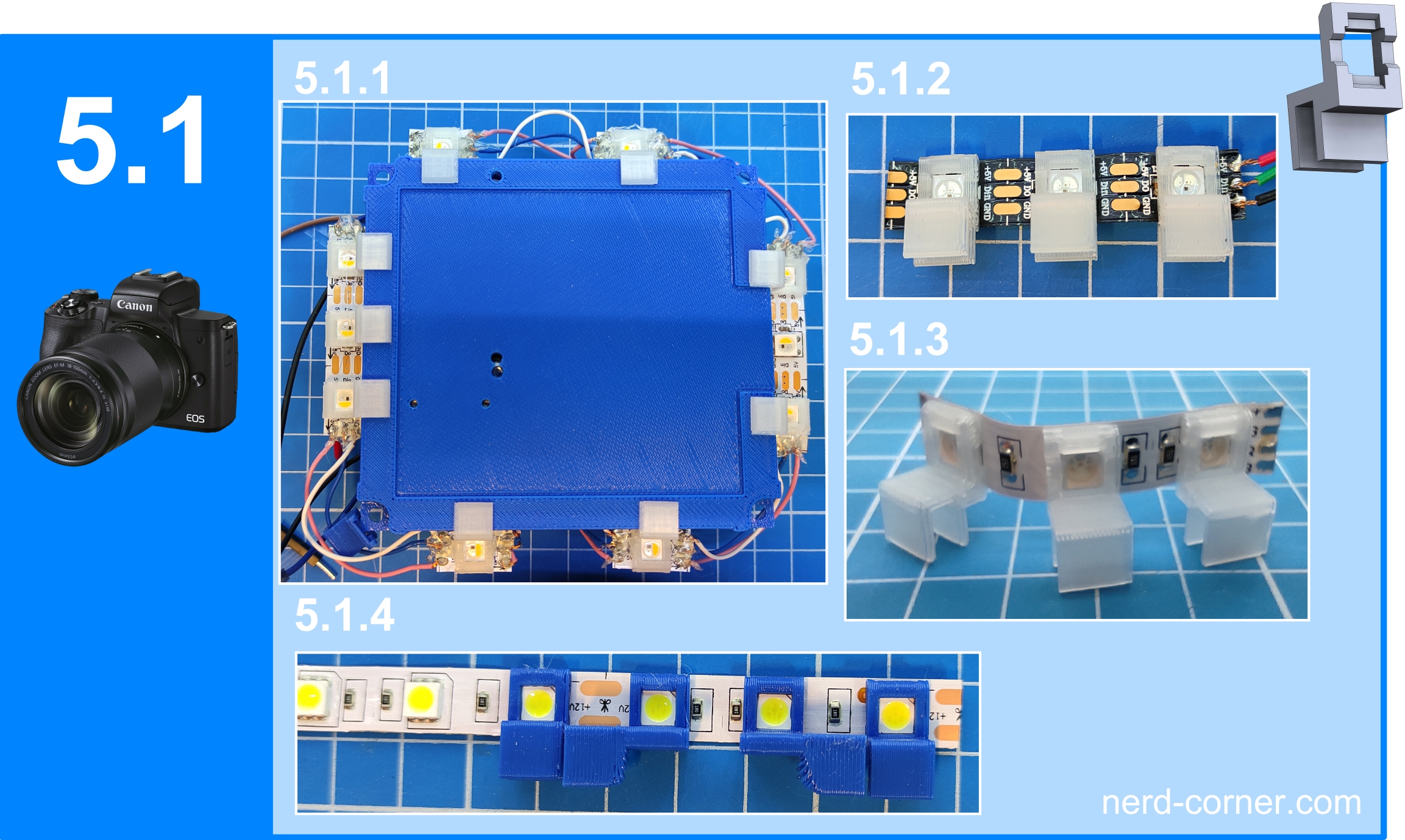
Application examples for the LED strip bracket
- 5.0.1, 5.0.2 WS2812B 60 LED/m
- 5.0.3 RGW on circuit board
- 5.0.4 WS2812B 144 LED/m (only every second LED can be clipped)
- 5.1.1 SK6812 soldered to carrier plate clamped
- 5.1.2 WS2812B soldered three pieces
- 5.1.3 RGW
- 5.1.4 CW with side clips right and left