

Tea lights are practical and create a pleasant Christmas atmosphere. Meanwhile, LED tea lights are also very popular. They usually have a battery as their energy supply. They are often operated with the CR2032 button cell. This has a voltage of 3V and the tea lights light up between 3 and 8 hours with one battery charge. After that, you have to change the battery. This bothers me because it is a lot of work and I have a guilty conscience. I would find it better to supply the tea lights with power permanently via a cable.
You might also be interested in: 3D printed battery container

List of components
- LED tealightset
- Button cell CR2032
- Jumper cables
- Screws
Procedure
First, I ordered a set of LED tea lights. I measured it and examined whether it could be connected to a cable. I was quite surprised by the technique of how the LED gets power from the battery. It is simple but well thought out! With the on/off switch, a metal pin is pushed to the edge of the battery. This edge is the positive pole. The other metal pin is fixed in the housing and permanently touches the bottom of the battery. The bottom is the negative pole. The metal pins reminded me of pins on jumper cables. You can see how I connected the cables to the tea lights in the following series of pictures.
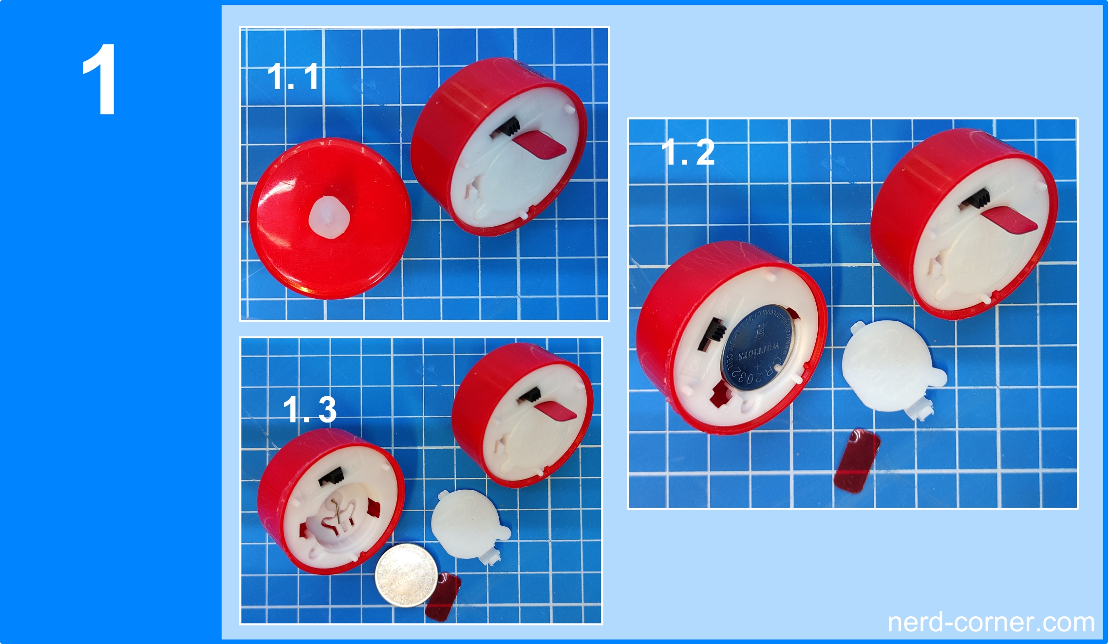
First, the cover and contact foil must be removed. Then the battery is removed.
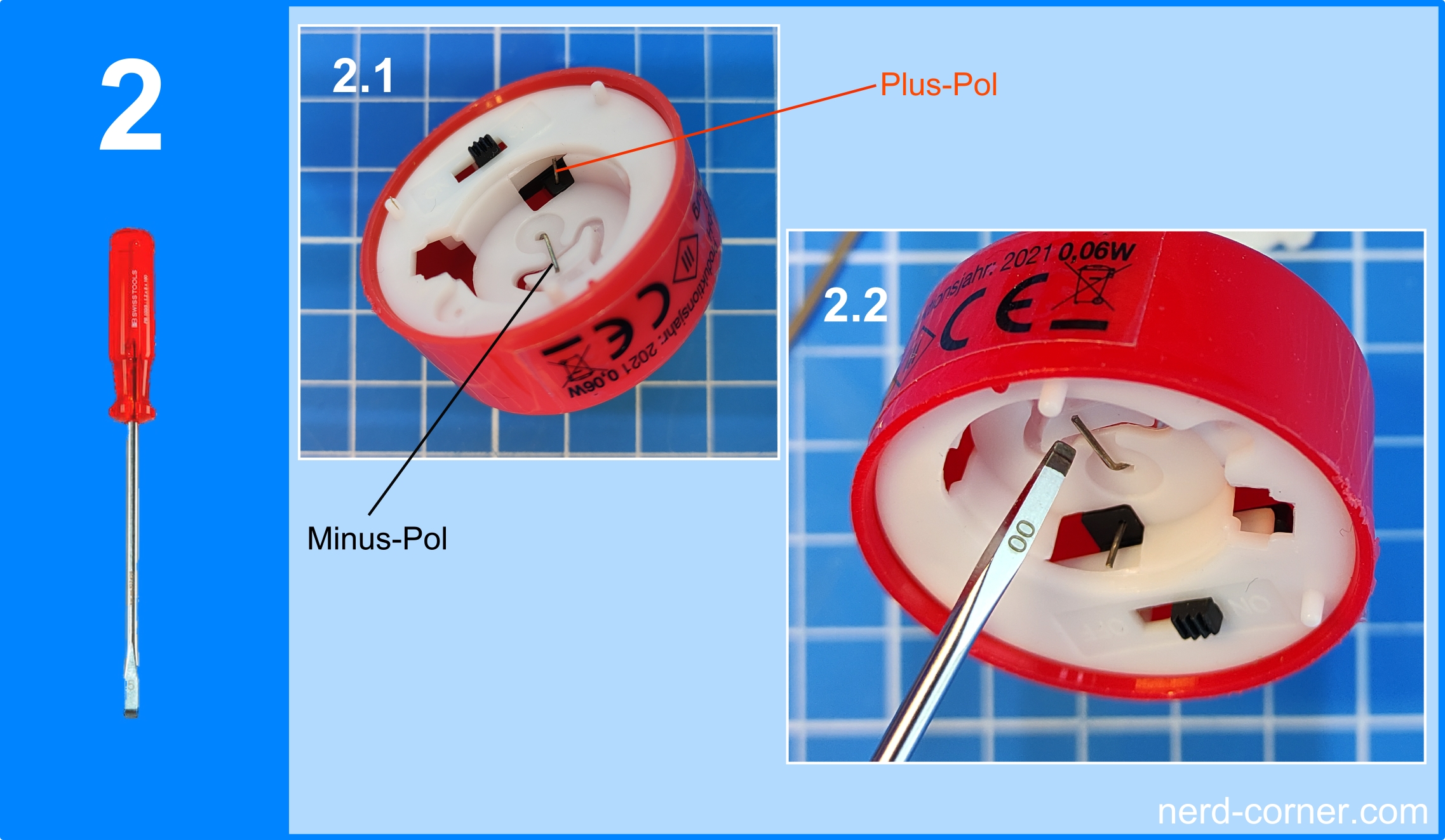
The two current collectors are now visible in the battery compartment. The negative pole is brought into the vertical position using a screwdriver or pliers.
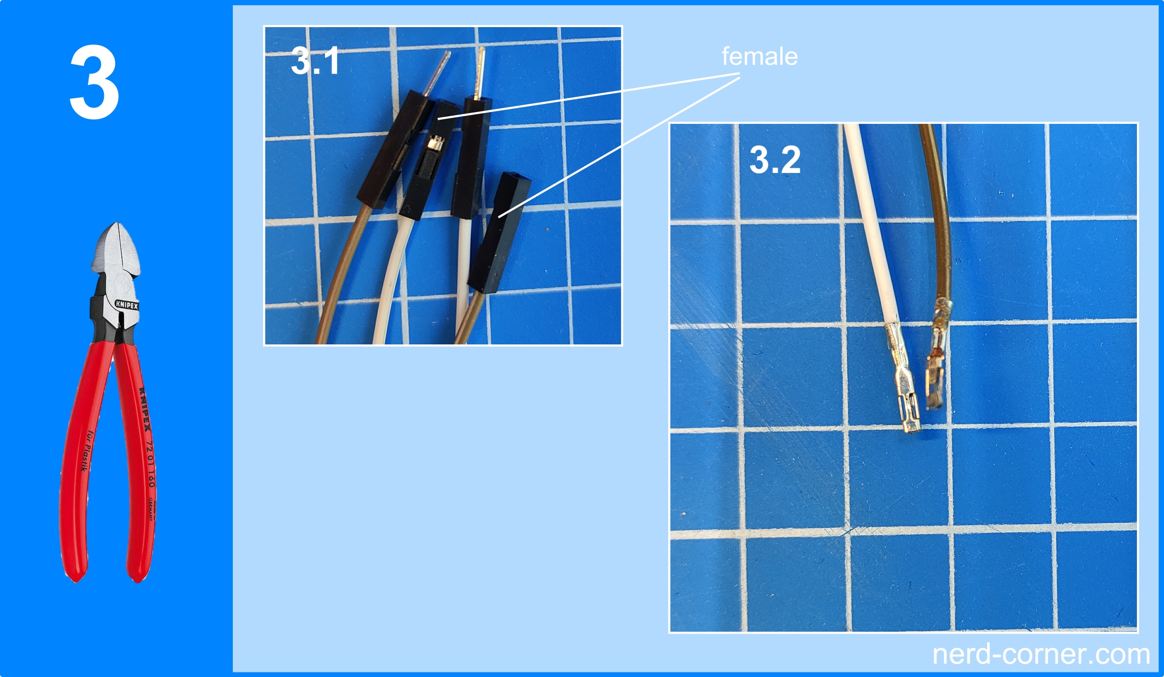
Then remove the black plastic cover (female) from both jumper cables with side cutters. But be careful not to damage or crush the metal clamps!
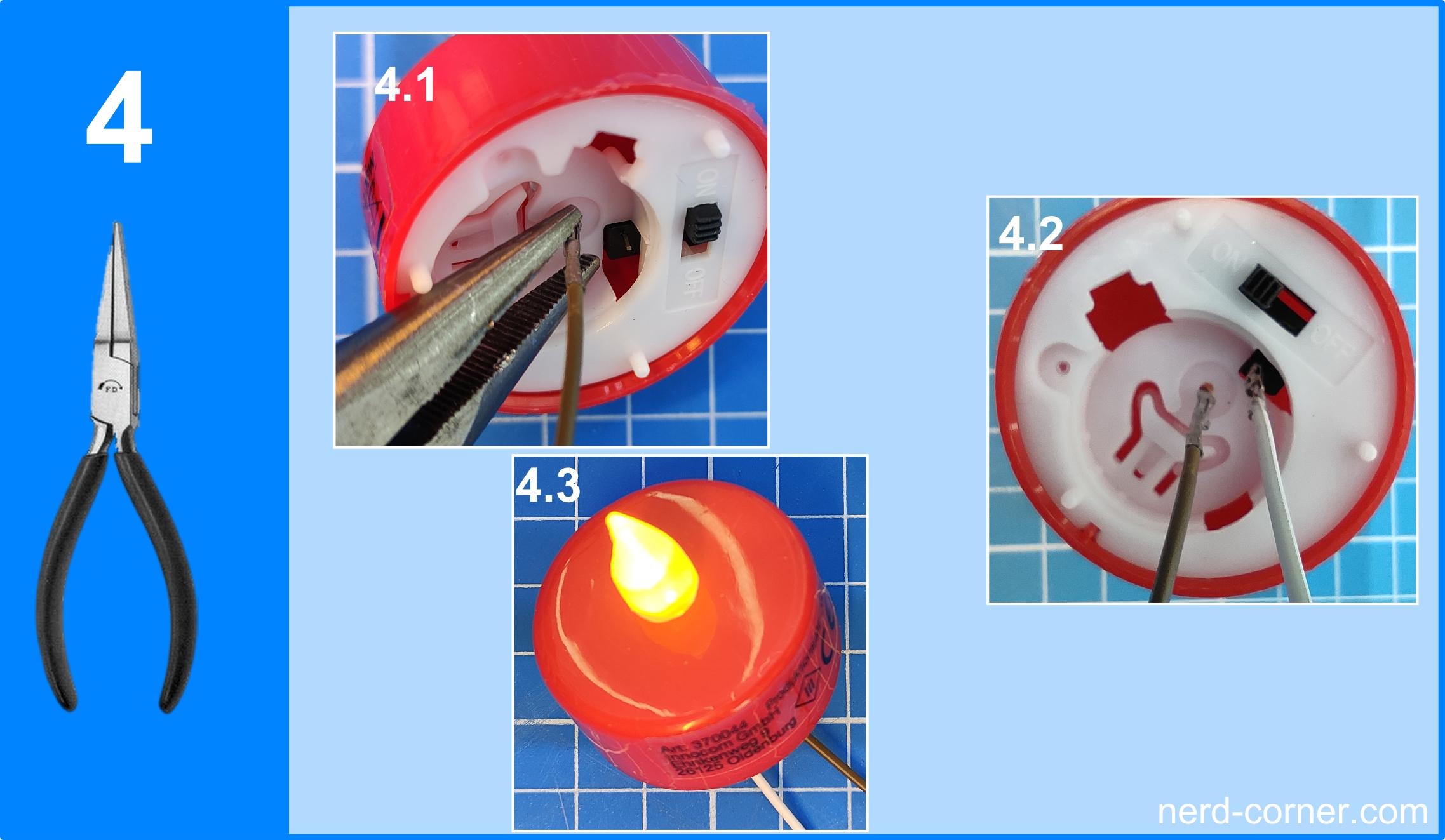
A jumper cable is pushed over the pin at the positive terminal and at the negative terminal and pressed on. Afterwards, the holding capacity of the press connection should be tested. When the metal clamps are firmly seated on the pin, the function of the LED should be checked. For example, by removing the battery.
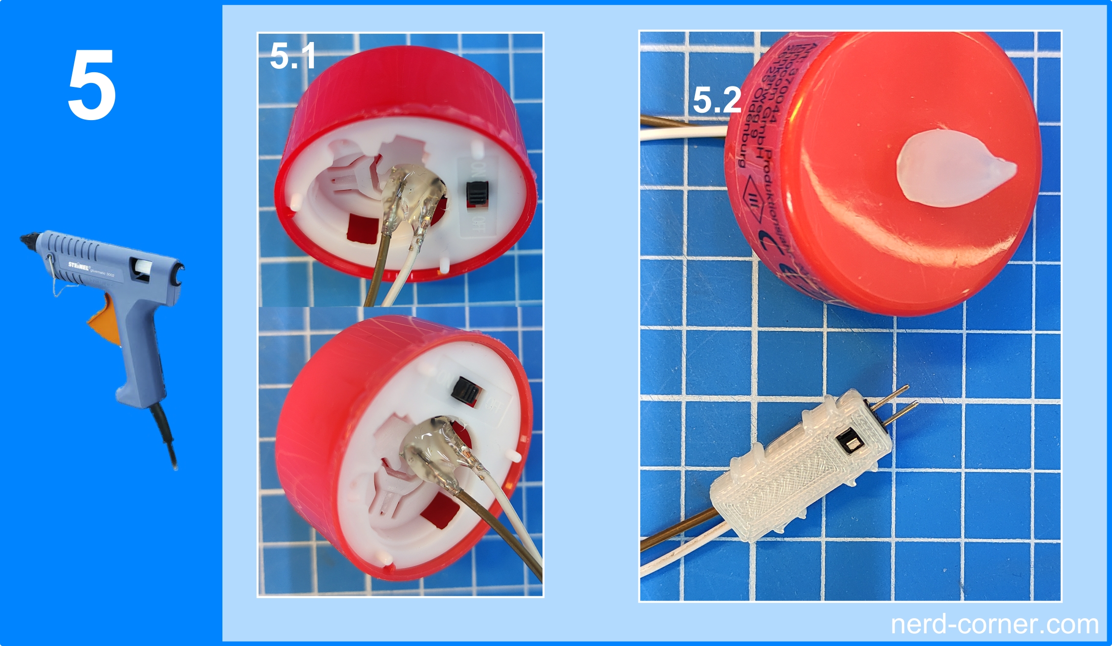
The cables are fixed with hot glue. Finally, after checking the function of the LED again, I attach a connector housing to the cables. You can find out how to construct such a connector housing here.
Secondly, I need a holder for my wired tea lights. I want to design the holder myself on the CAD and then print it out on the 3D printer. You can see how to design such a tea light holder in Solidworks in the video below:
After the tealight holder has been designed and printed, it is painted. Then the wired LED tea light can be mounted in the holder. Of course, the holder should be properly deburred beforehand. You can see the procedure in the next picture.

When using the tealight holder shown here, make sure that the cables are fed through the hole provided for this purpose. Please also take care to insert the cables one after the other into the hole in step 6.4.
Power supply
The third step is the power supply for the tea lights. For this I use a USB power supply with 5V and a step down module like the LM2596s. The voltage converter is supposed to provide me with the 3V that the tea lights need. Fortunately, I have constructed some housings for the LM2596 in the past that I can use here.
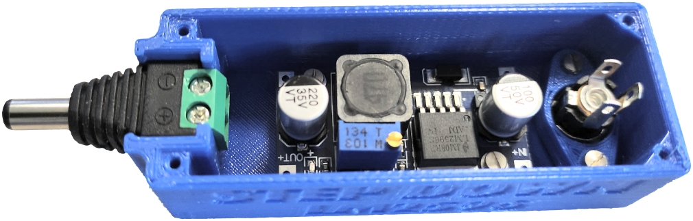

With the LM2596 used here, I reduce the voltage from the USB charger from 5V to 3V for the LED. You can also apply a voltage of less than 3V, in which case only the luminosity of the LEDs is reduced. The arrangement of the holders in the picture is only an example.
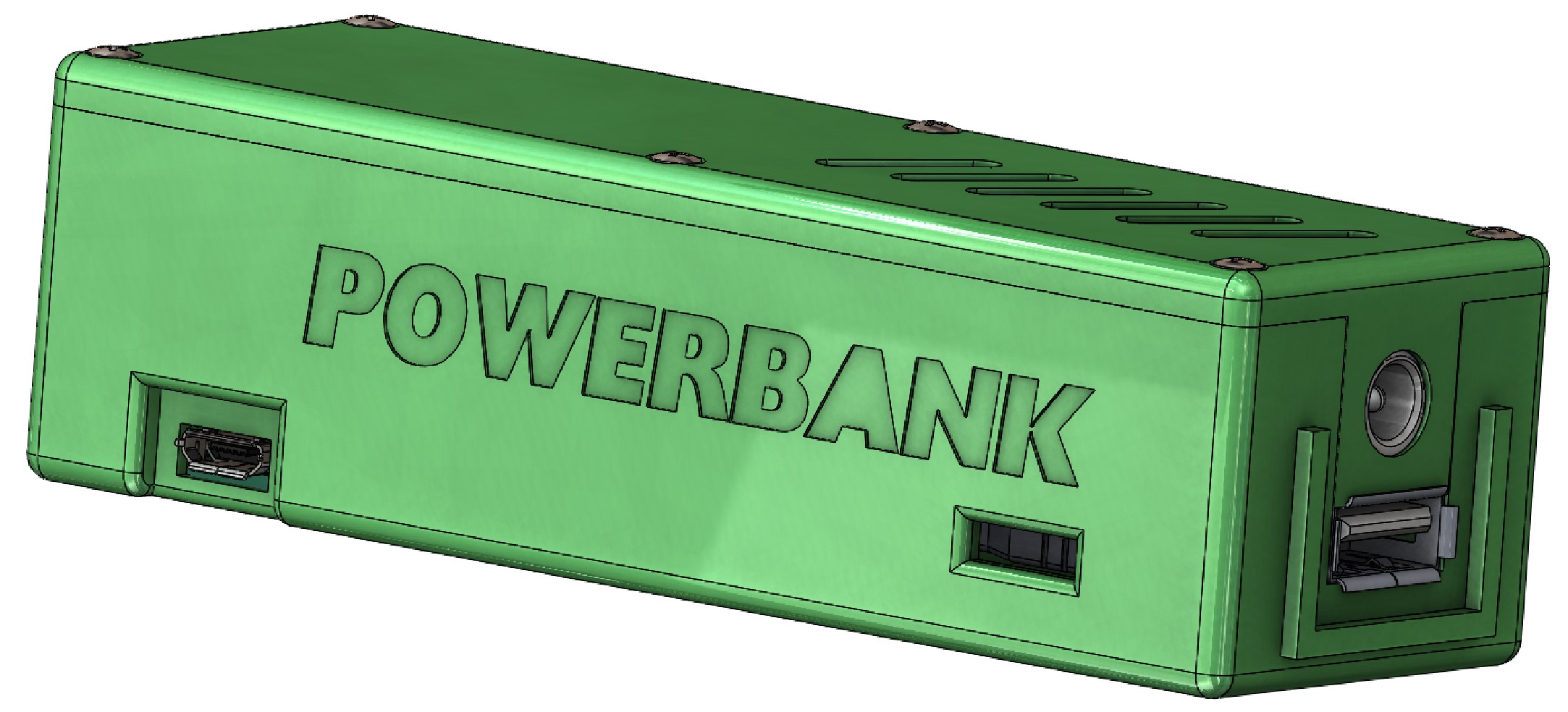
If you need an independent power source, e.g. a power bank, you can use my power bank with 3V output.
Assembly

Different screws can be used for mounting the tea light holders. Depending on the surface, you can use wood screws or cylinder head screws, for example. Alternatively, you can also screw the holder directly to the wall with the help of dowels. The only thing to note is that the screw head must be larger than 7 mm and smaller than 11 mm in diameter. The hole for the screws has a diameter of 5 mm. The hole for the cables lies vertically on the centre line of the screw hole and the centre distance to this is exactly 7 mm. The diameter of the cable hole is 4.5 mm.


